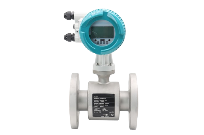
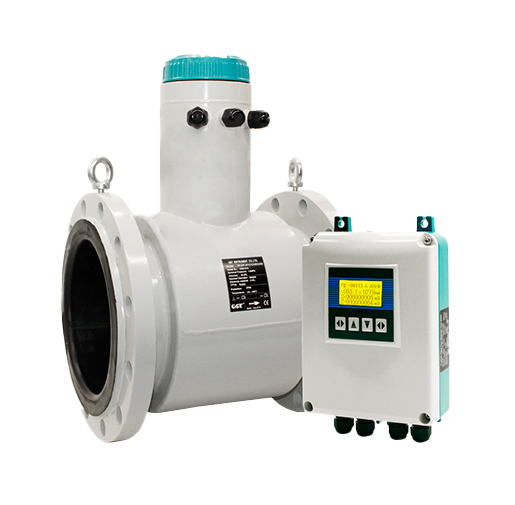
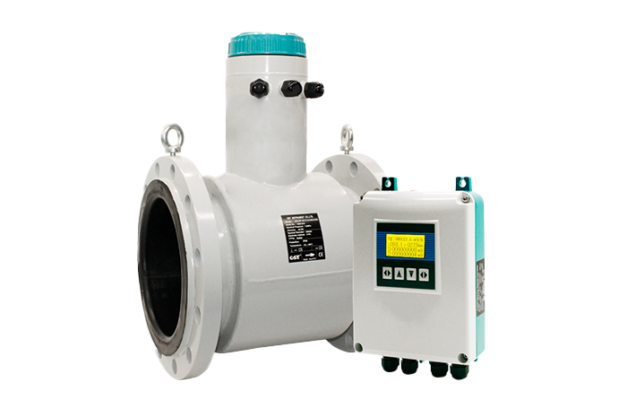
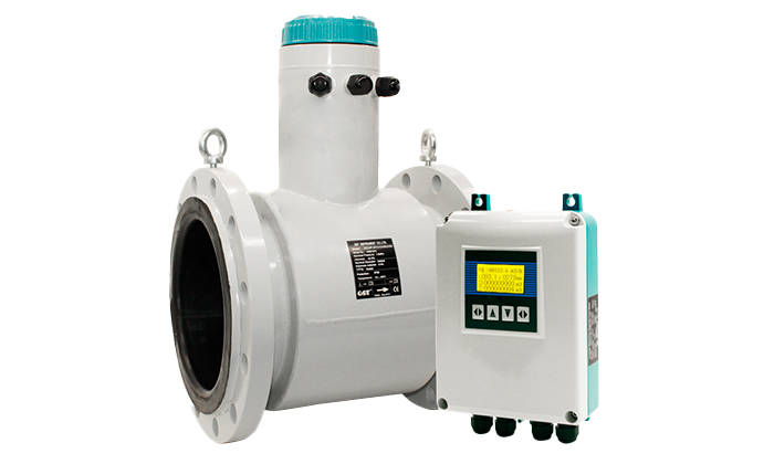
The non-full pipe flow meter is a kind of automatic flow measuring instrument that continuously measures the fluid flow in open pipelines (such as half-pipe sewage pipes and large flow pipes without overflow weirs) by using the flow rate-area method. It can measure and display the instantaneous flow rate, flow rate, cumulative flow rate and other data. It is especially suitable for the needs of measuring places such as municipal rainwater, waste water, sewage discharge and irrigation water pipes.
The non-full tube flow meter is composed of an electromagnetic flow rate sensor, an ultrasonic water level sensor and a flow rate display. It continuously measures the flow rate and level of the fluid in the pipe. The user only needs to enter the inner diameter of the round pipe or the width of the square pipe. The non-full-tube flow meter will automatically calculate the flow rate in the pipeline, and automatically display the instantaneous flow rate, flow rate, cumulative flow rate and other measurement parameters in the pipeline.
Partially filled pipe flow meter is not affected by changes in fluid density, viscosity, temperature, pressure, and conductivity. The sensor induced voltage signal is linearly related to the average flow rate, so the measurement accuracy is high.
There is no obstruction in the measuring pipe, so there is no additional pressure loss; there are no moving parts in the measuring pipe, so the sensor life is extremely long.
Because the induced voltage signal is formed in the entire space filled with magnetic field and is the average value on the pipe loading surface, the straight pipe section required by the sensor is short and the length is 5 times the pipe diameter.
In the sensor part, only the lining and the electrode are in contact with the liquid to be measured. As long as the electrode and the lining material are properly selected, they are resistant to corrosion and wear.
| Measuring Pipe Size | DN200-DN3000 |
| Connection | Flange |
| Liner Material | Neoprene/Polyurethane |
| Electrode Marerial | SS316, TI, TA, HB, HC |
| Structure Type | Remote Type |
| Accuracy | 2.5% |
| Output Signal | Modbus RTU, TTL electrical level |
| Communication | RS232/RS485 |
| Flow speed range | 0.05-10m/s |
| Protection Class | Converter: IP65 Flow Sensor: IP65(standard), IP68(optional) |
![]() Drawing ( DIN Flange ) |
||||||
| Diameter (mm) |
Nominal pressure |
L(mm) | H | φA | φK | N-φh |
| DN200 | 0.6 | 400 | 494 | 320 | 280 | 8-φ18 |
| DN250 | 0.6 | 450 | 561 | 375 | 335 | 12-φ18 |
| DN300 | 0.6 | 500 | 623 | 440 | 395 | 12-φ22 |
| DN350 | 0.6 | 550 | 671 | 490 | 445 | 12-φ22 |
| DN400 | 0.6 | 600 | 708 | 540 | 495 | 16-φ22 |
| DN450 | 0.6 | 600 | 778 | 595 | 550 | 16-φ22 |
| DN500 | 0.6 | 600 | 828 | 645 | 600 | 20-φ22 |
| DN600 | 0.6 | 600 | 934 | 755 | 705 | 20-φ22 |
| DN700 | 0.6 | 700 | 1041 | 860 | 810 | 24-φ26 |
| DN800 | 0.6 | 800 | 1149 | 975 | 920 | 24-φ30 |
| DN900 | 0.6 | 900 | 1249 | 1075 | 1020 | 24-φ30 |
| DN1000 | 0.6 | 1000 | 1359 | 1175 | 1120 | 28-φ30 |
![]() lnstall at the lowest point and vertical upward direction Don't install at the highest point or vertical downward diection |
![]() When drop is more than 5m, install exhaust valve at the downstream |
![]() lnstall at the lowest point when used in open drain pipe |
![]() Need 10D of upstream and 5D of downstream |
![]() Dont' install it at the entrance of pump, install it at the exit of pump |
![]() lnstall at the rising direction |