The working principle of the Coriolis mass flowmeter
The Coriolis mass flowmeter is an instrument that measures the mass flow rate of fluids by utilizing the Coriolis effect. The Coriolis effect refers to the fact that when a fluid passes through a laterally constrained pipe, due to the fluid’s own rotation and the collisions between fluid molecules, a lateral temperature difference perpendicular to the fluid flow direction and the magnetic field direction will be generated. The Coriolis effect is caused by the interaction between the magnetic field induced by the current passing through a laterally constrained wire and the electrons and ions in the fluid.
1. Working principle of Coriolis flowmeter
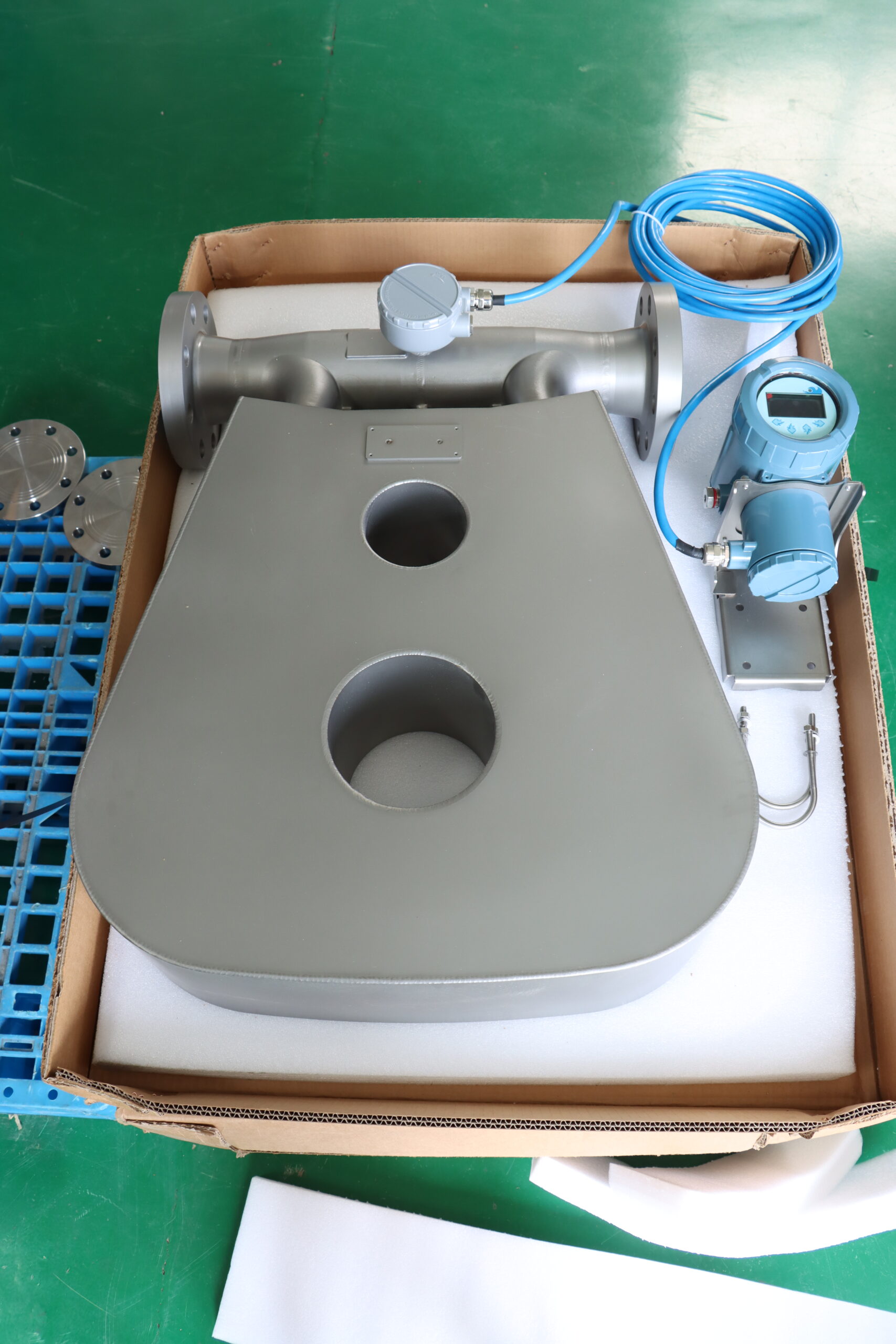
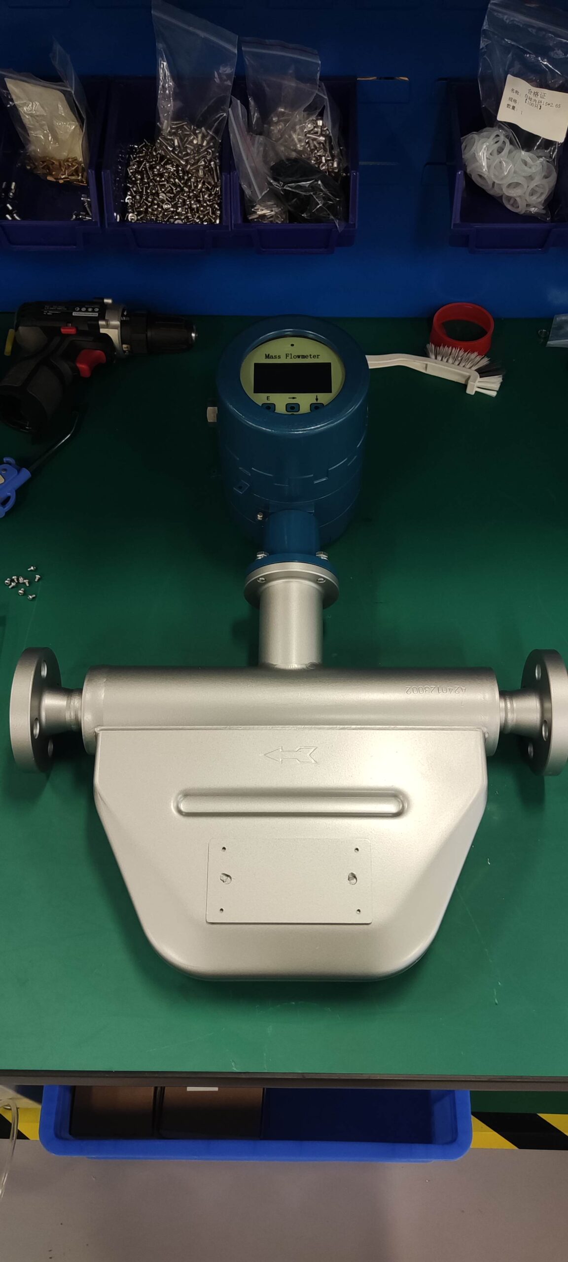
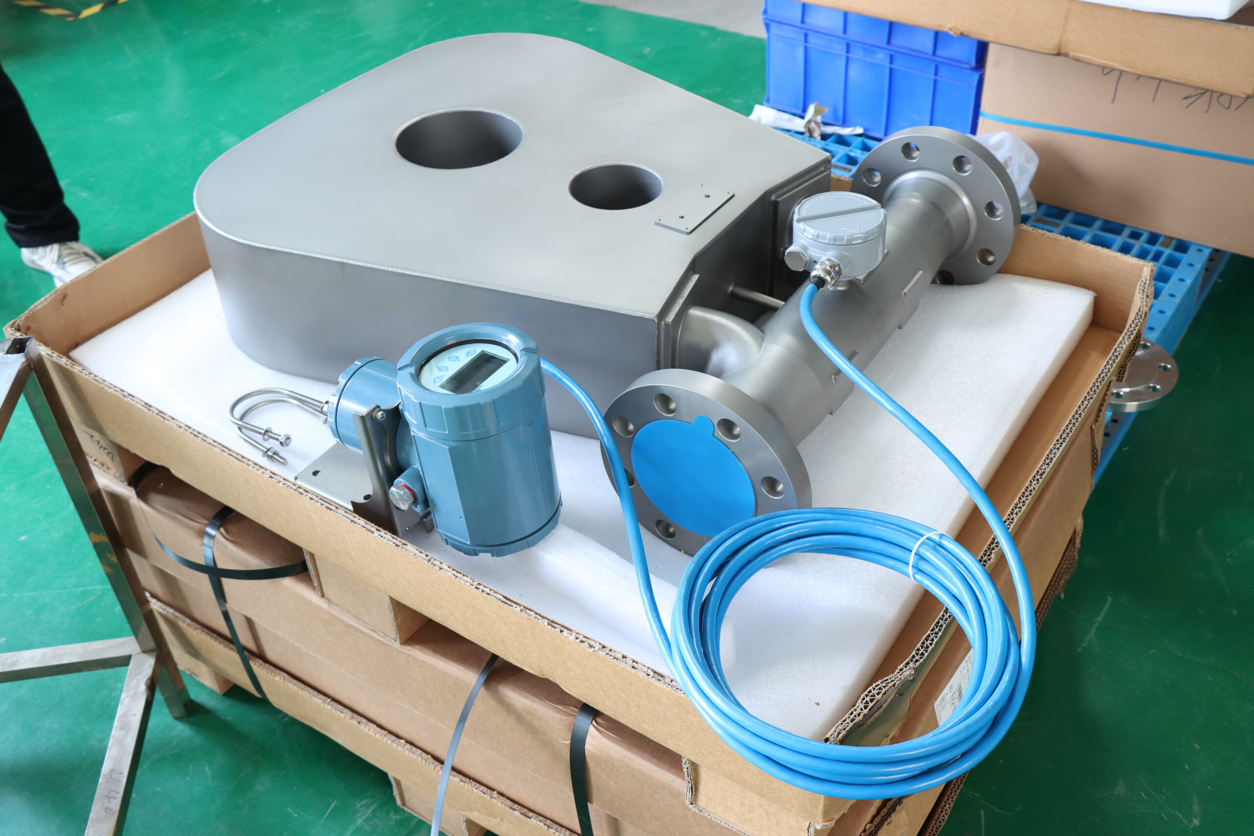
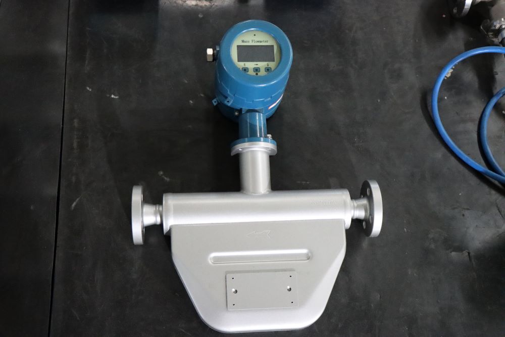
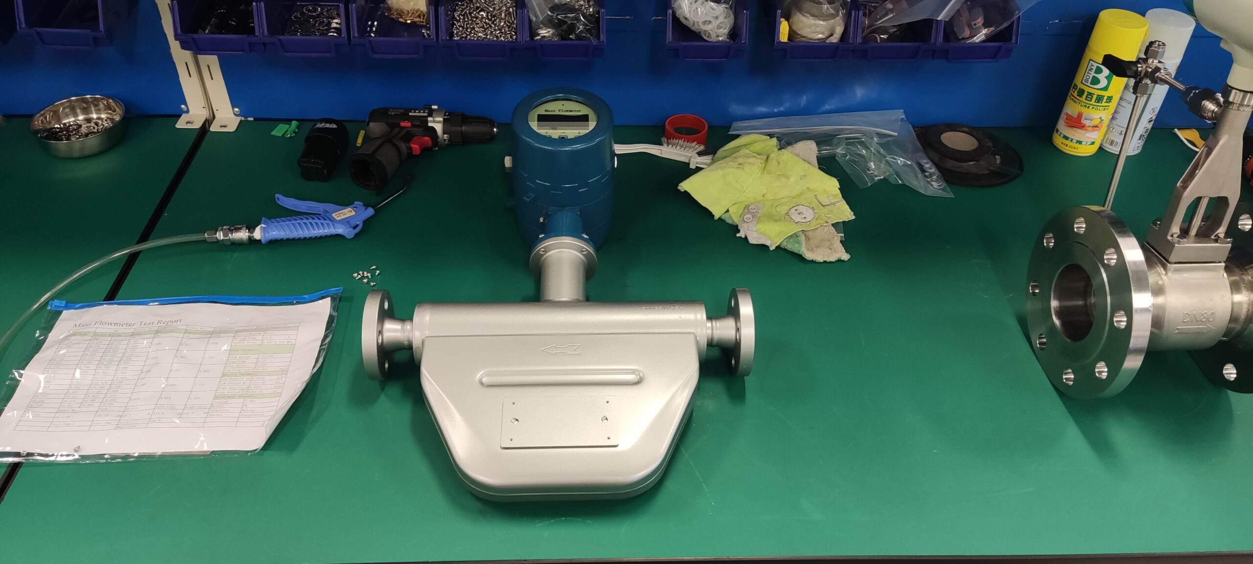
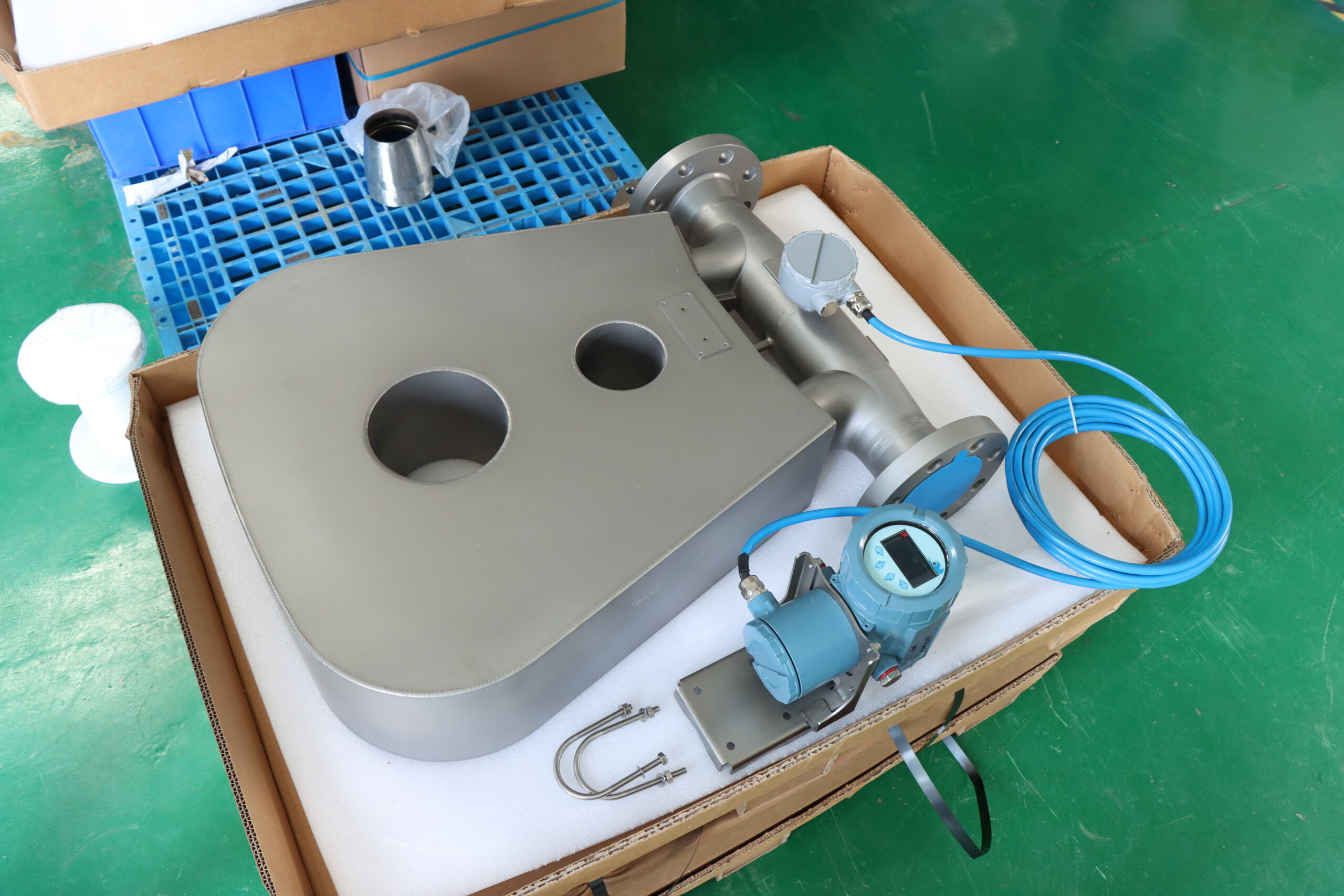
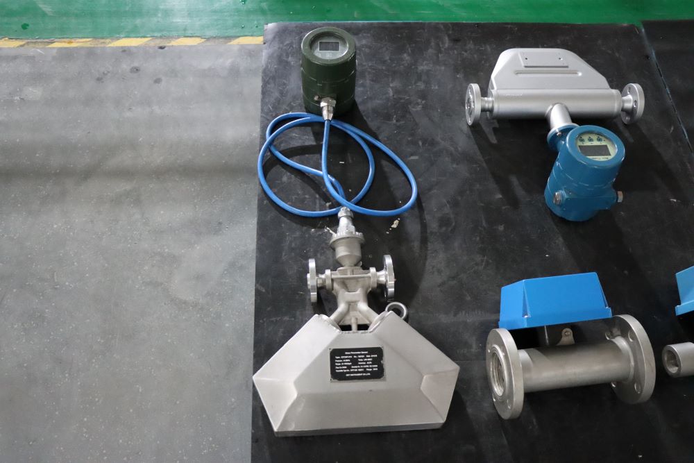
The Coriolis flowmeter operates based on the principles of motion mechanics. When the process fluid enters the sensor, the fluid will separate. During the measurement process, the driving coil will excite the pipe to vibrate towards each other at its inherent resonant frequency. When the pipeline vibrates, the voltage generated on each sensor will form a sine wave. This can represent the movement of one tube relative to another. The time lag between two sine waves is called Delta-T, and this value is proportional to the mass flow rate.
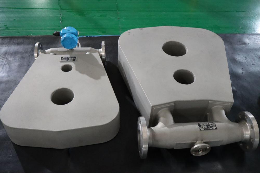
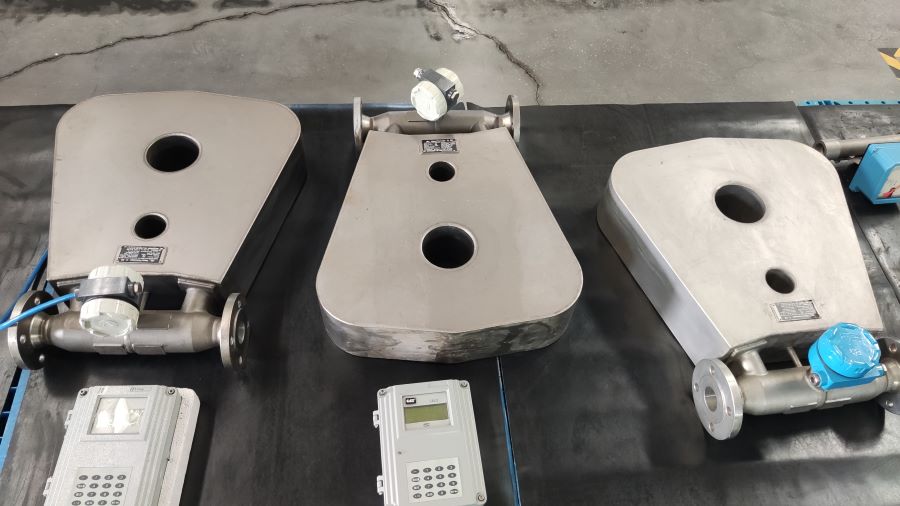
The Coriolis mass flowmeter (also known as the Coriolis mass flowmeter) is a type of mass flow instrument with relatively high measurement accuracy. The principle is based on Newton’s second law: when a fluid flows in a vibrating tube, a Coriolis force proportional to the mass flow rate will be generated. When no fluid flows through, the vibrating tube does not twist, and the signals detected by the electromagnetic signal detectors on both sides of the vibrating tube are in phase. When fluid passes through, the vibrating tube will twist under the action of torque, and there will be a phase difference between the two detectors. The transmitter measures the lag time between the left and right detection signals. Multiplying this time difference by the flow calibration coefficient can determine the mass flow rate.
2. Functional features of Coriolis flowmeters
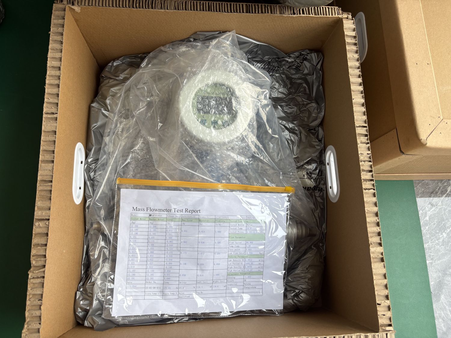
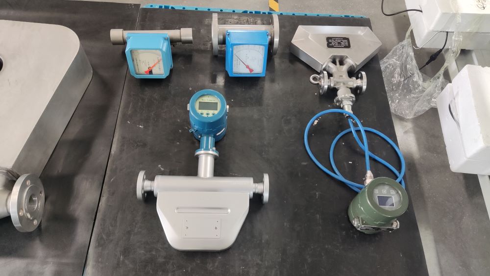
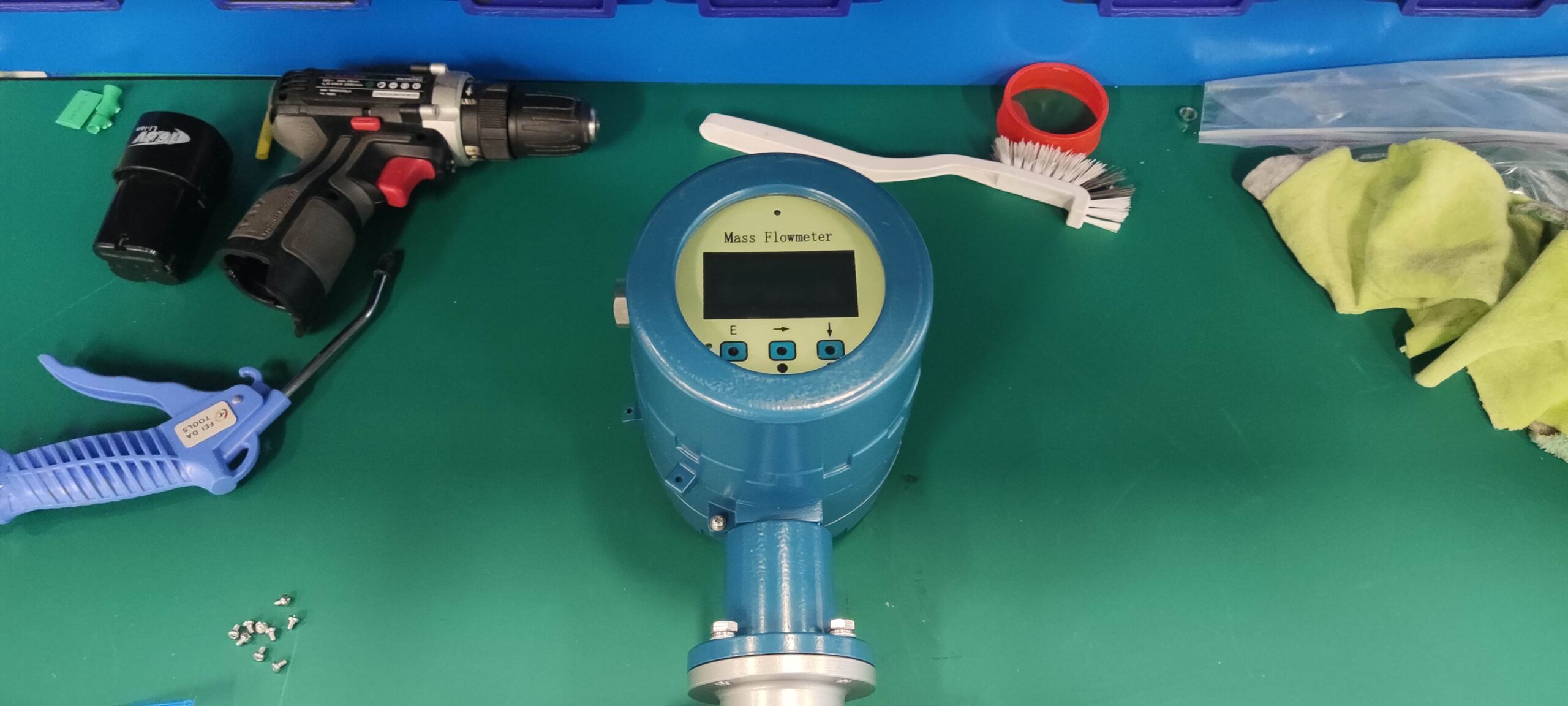
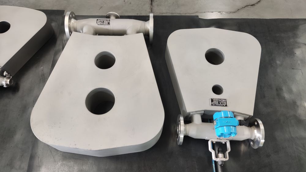
The Coriolis mass flowmeter has a high measurement accuracy, ensuring an accuracy of 0.1% to 0.2%. It can withstand low-temperature media, has a relatively small vibration amplitude, no moving parts, operates reliably and stably, is easy to operate and simple, has a low maintenance rate and is convenient to maintain. It can directly measure the mass flow rate of the medium and the real-time density of the fluid. It can be said to be an extremely convenient density instrument. It features integrated temperature and pressure compensation, directly outputs mass or standard square meters. The instrument is equipped with a self-checking program, making fault phenomena clear at a glance. It offers multiple outputs and can remotely transmit various data. It can be made of multiple anti-corrosion and high and low temperature resistant materials. Users can choose from optional small signal cut-off, nonlinear correction, and filtering time.
When the fluid medium in the process pipeline contains gas and the gas content exceeds a certain value, it will significantly affect the measurement value of the Coriolis force mass flowmeter, leading to inaccurate measurement results. Therefore, the Coriolis force mass flowmeter cannot be used for the measurement of gas-liquid two-phase fluids.
The Coriolis force mass flowmeter also has relatively low requirements for on-site installation. This is because the flow velocity distribution corresponding to the Coriolis force mass flowmeter is not very sensitive. Therefore, the requirements for the upper and lower straight pipe sections during installation are not high.
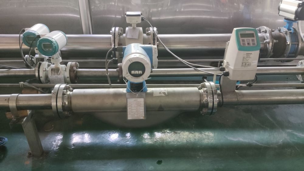
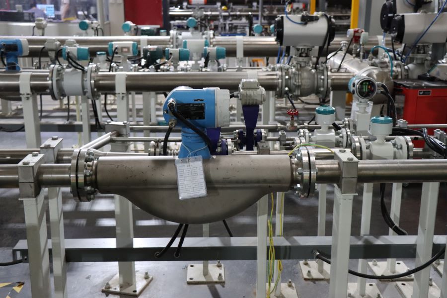
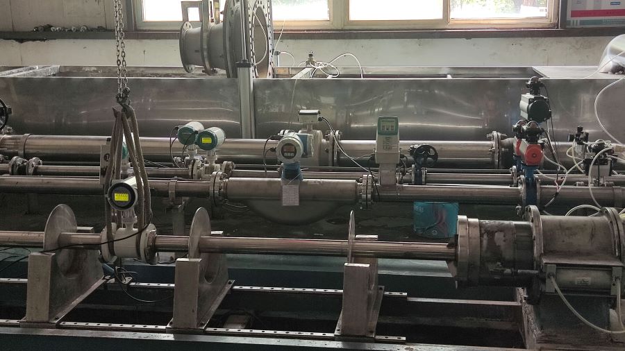
3. Installation requirements for Coriolis flowmeters
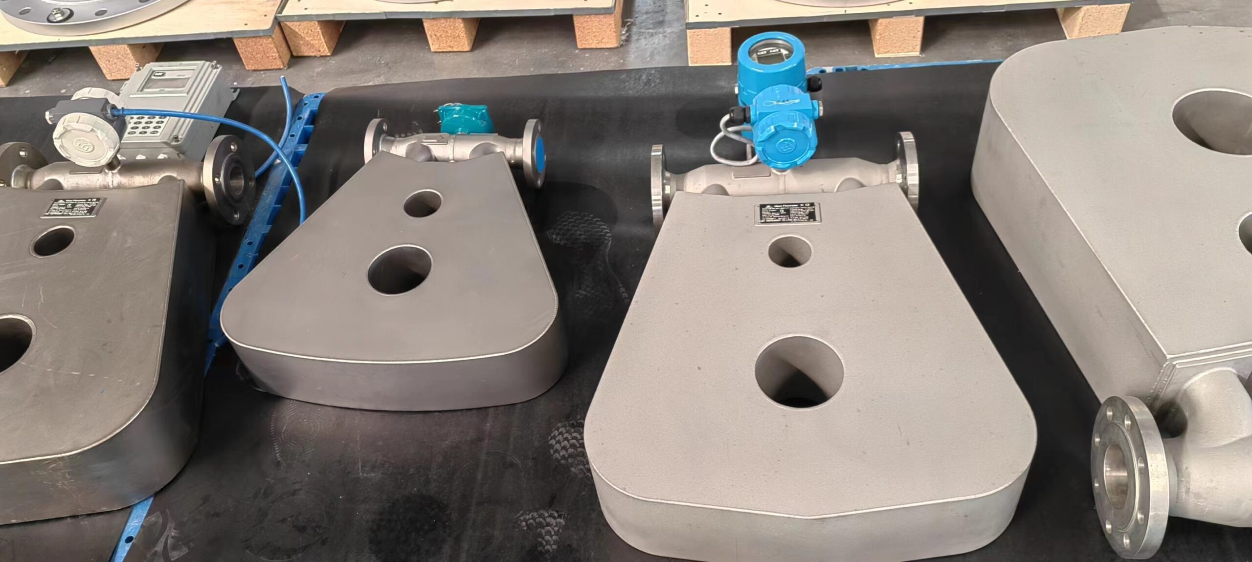
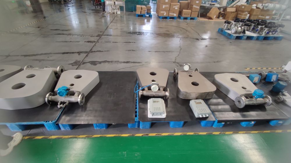
The installation position of the Coriolis mass flowmeter must avoid interference sources that can cause pipeline vibration, such as pumps on process pipelines. If the sensors are used in series on the same pipeline, the mutual influence caused by resonance should be avoided. The distance between the sensors should be at least three times the width of the sensor’s external dimensions.
② The installation location should pay attention to the expansion or deformation of the process pipeline caused by temperature changes. It must not be installed near the expansion joint of the process pipeline. If it is installed near this position, the expansion and contraction of the pipeline will cause lateral stress, which will change the zero point of the sensor and affect the measurement accuracy.
③ The installation location should also be away from industrial electromagnetic interference sources, such as transformers, high-power motors and other equipment. Otherwise, the measuring tube in the sensor will vibrate and be disturbed, and the weak signal monitored by the speed sensor may be submerged in the noise of electromagnetic interference. Moreover, it should be at least 5 meters away from the interference source equipment.
The installation position of the sensor should ensure that the fluid in the pipeline always fills the sensor measurement tube and there is a certain pressure build-up. Therefore, the installation position should be at the lower end of the pipeline.
In conclusion, the Coriolis mass flowmeter measures the mass flow of fluids based on the Coriolis effect principle. It features high measurement accuracy, wide measurement range, strong anti-interference ability, and fast response speed. It is widely used in fields such as chemical engineering, power, petroleum, and natural gas.