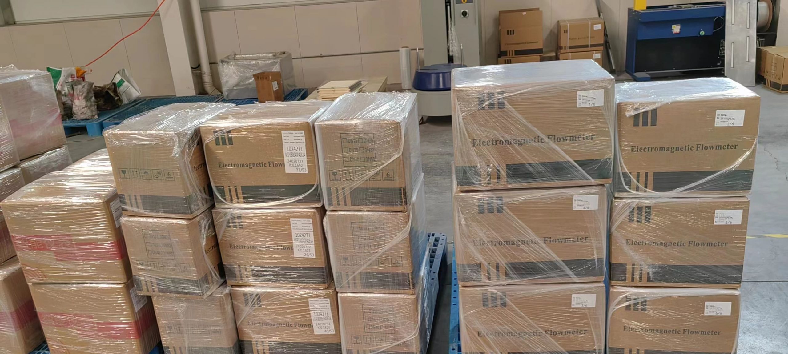
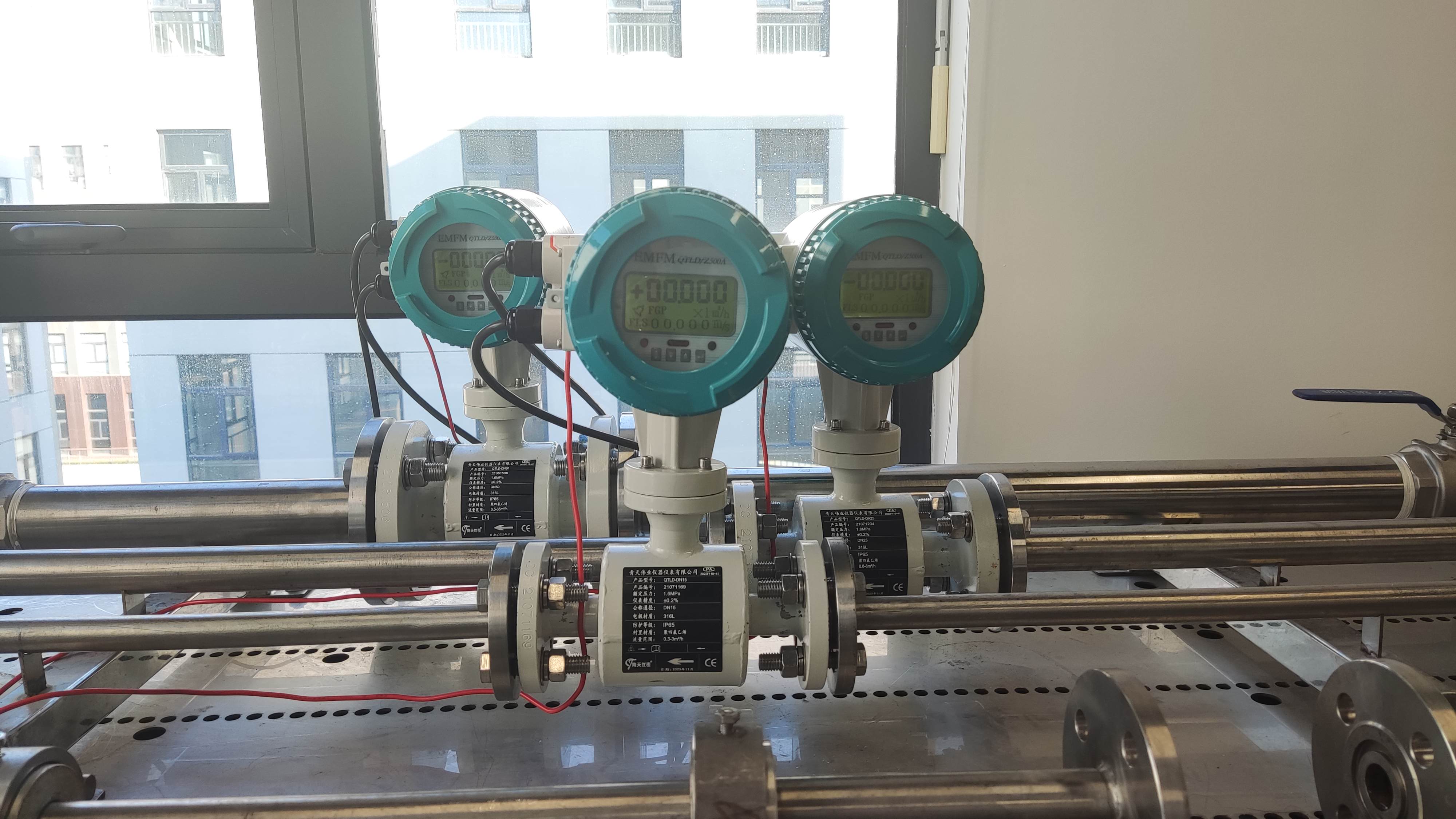
Selection and installation of electromagnetic flow meter
Reasonable selection and correct installation of the electromagnetic flowmeter is very important to ensure the measurement accuracy and extend the service life of the instrument. The following is a brief introduction to the selection of electromagnetic flowmeter principles, installation conditions and precautions for use.
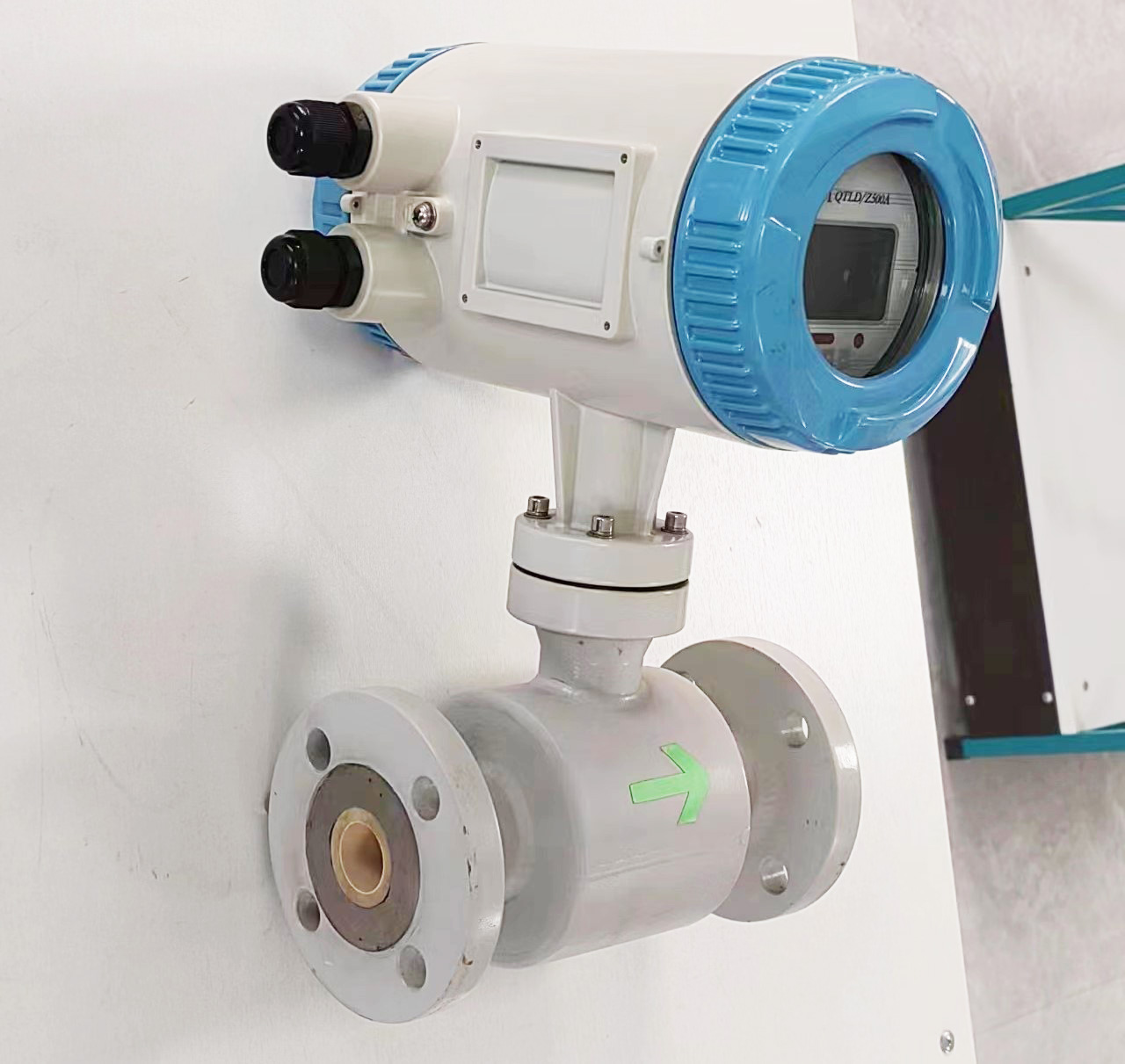
Electromagnetic flowmeter selection principle
The selection of electromagnetic flowmeter is mainly the correct selection of transmitter, and the converter only needs to be matched with it.
a. Selection of caliber and range
The transmitter caliber is usually selected to be the same caliber as the piping system. If the piping system is to be designed, the caliber can be selected according to the flow range and velocity. For electromagnetic flowmeters, the flow rate is more suitable for 2-4m/s. In special cases, such as with solid particles in the liquid, taking into account the wear situation, the usual flow rate is optional ≤3m/s for fluids that are easy to manage. Optional flow rate ≥2m/s. After the flow rate is determined, the transmitter aperture can be determined according to qv = D2.
The range of the transmitter can be selected according to two principles: first, the full scale of the instrument is greater than the expected flow value; Second, the normal flow rate is greater than 50% of the full scale of the instrument to ensure a certain measurement accuracy.
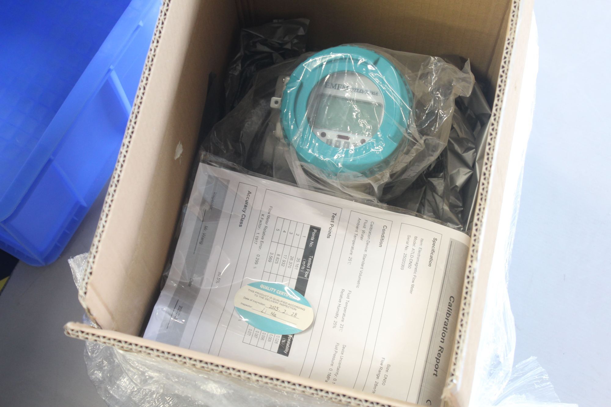
b. Selection of temperature and pressure
The electromagnetic flowmeter can measure the fluid pressure and temperature is limited. When selecting, the use pressure must be lower than the working pressure specified by the flowmeter. At present, the working pressure specifications of the domestic production of electromagnetic flowmeters are:
50mm diameter, working pressure is 1.6MPa;
900mm diameter, working pressure is 1MPa;
The diameter is greater than 1000mm, and the working pressure is 0.6MPa.
If there are special requirements for the pressure resistance of the transmitter, you can negotiate with the manufacturer. Some manufacturers have been able to manufacture electromagnetic flow transmitters with a pressure of 32MPa.
The operating temperature of the electromagnetic flowmeter depends on the lining material used, generally 5-70 ° C. If special treatment.
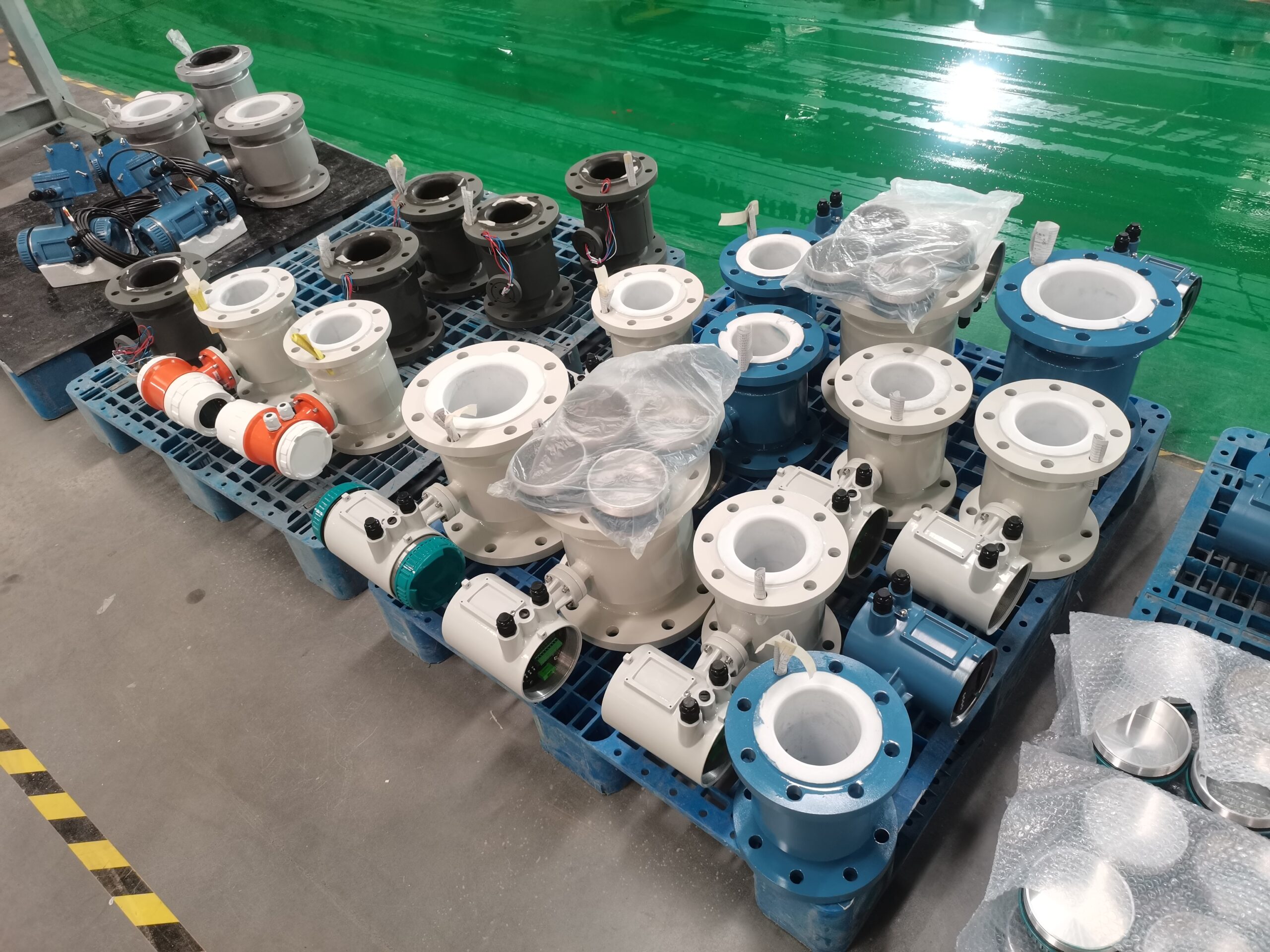
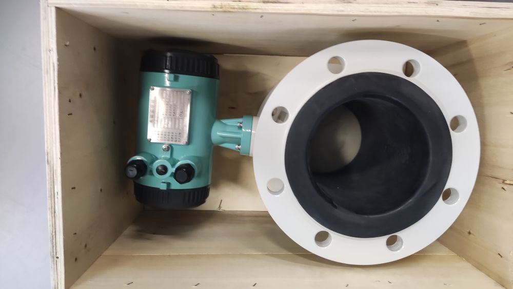
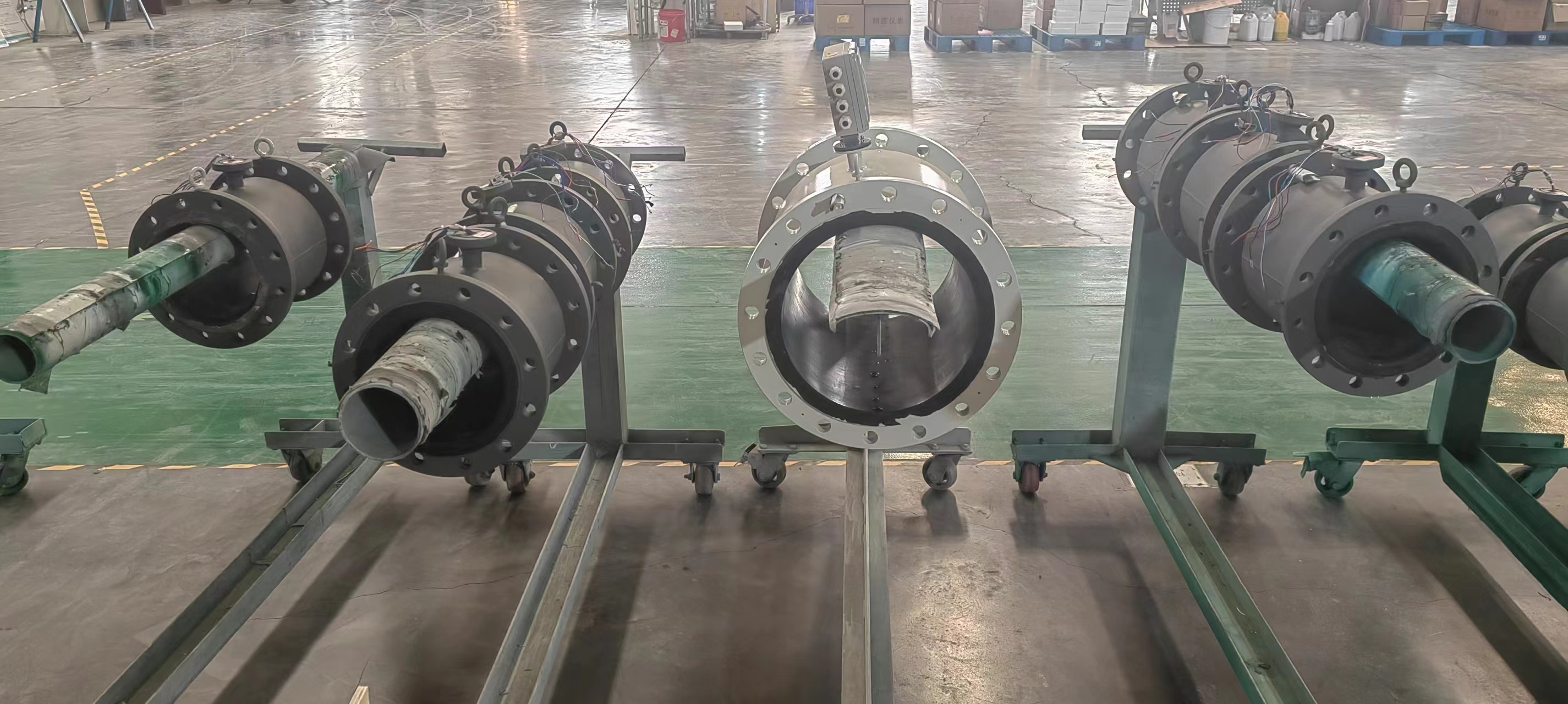
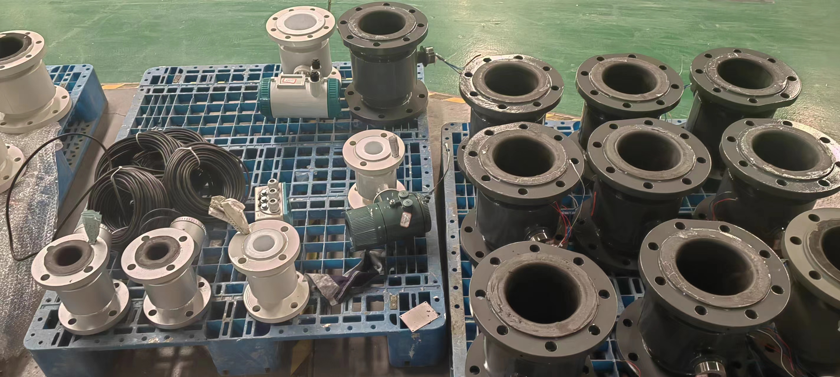
c. Selection of lining material and electrode tree material
The lining material and electrode material of the transmitter must be correctly selected according to the physical and chemical properties of the medium, otherwise the instrument will be quickly damaged due to the corrosion of the lining and electrode, and the highly corrosive medium is easy to cause accidents once it leaks. Therefore, the electrode and lining material must be carefully selected according to the specific measurement medium in the production process.
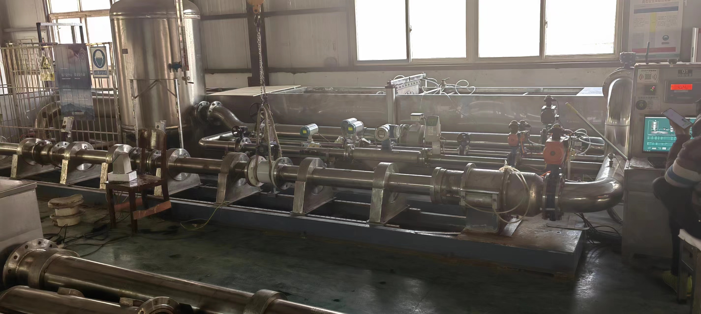
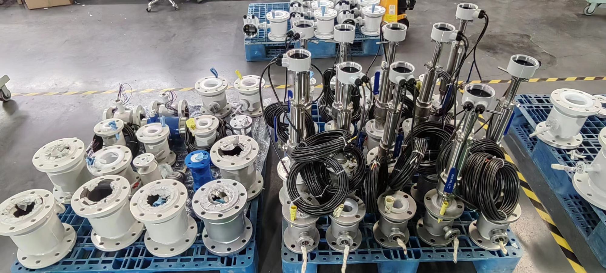
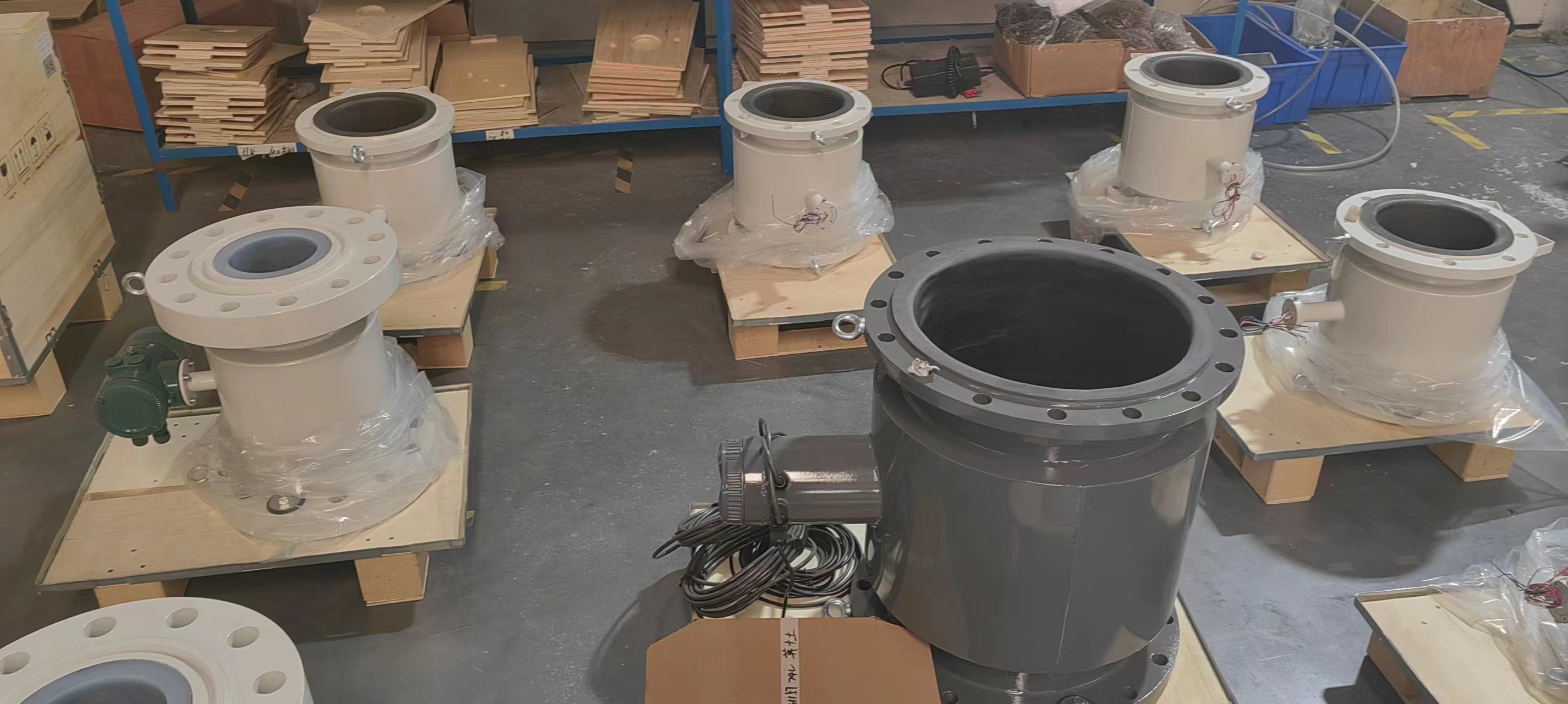
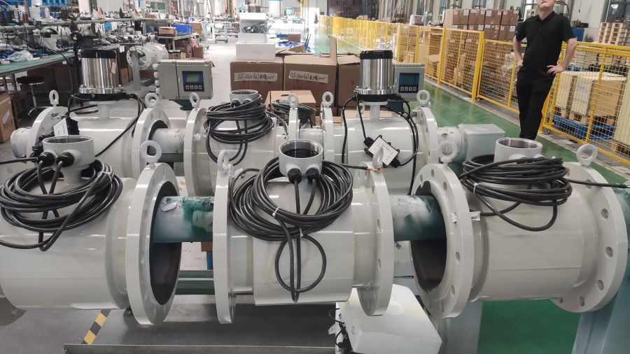
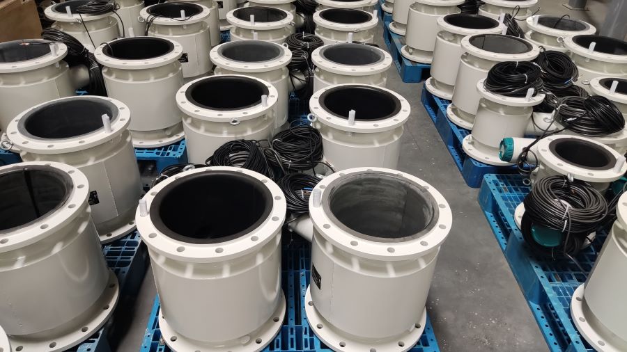
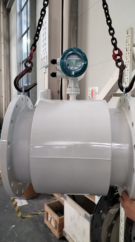
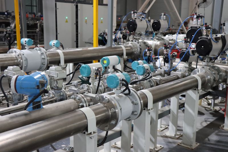
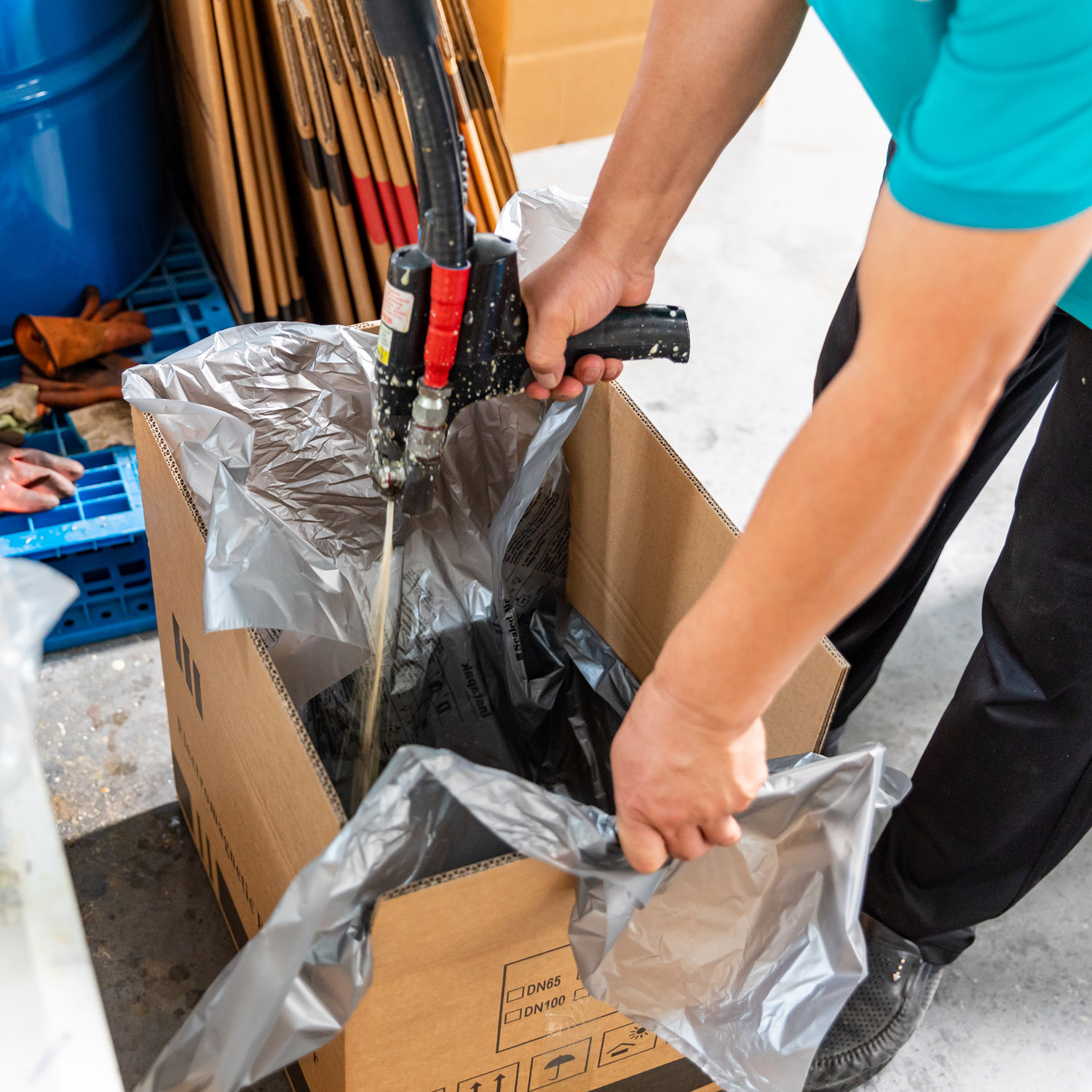
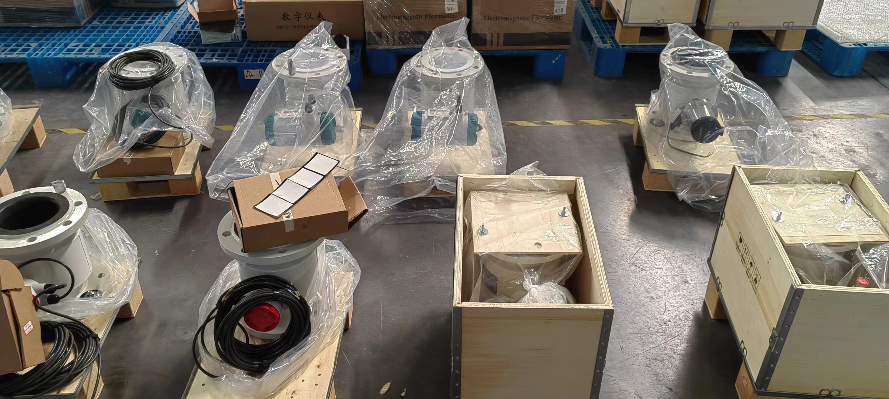
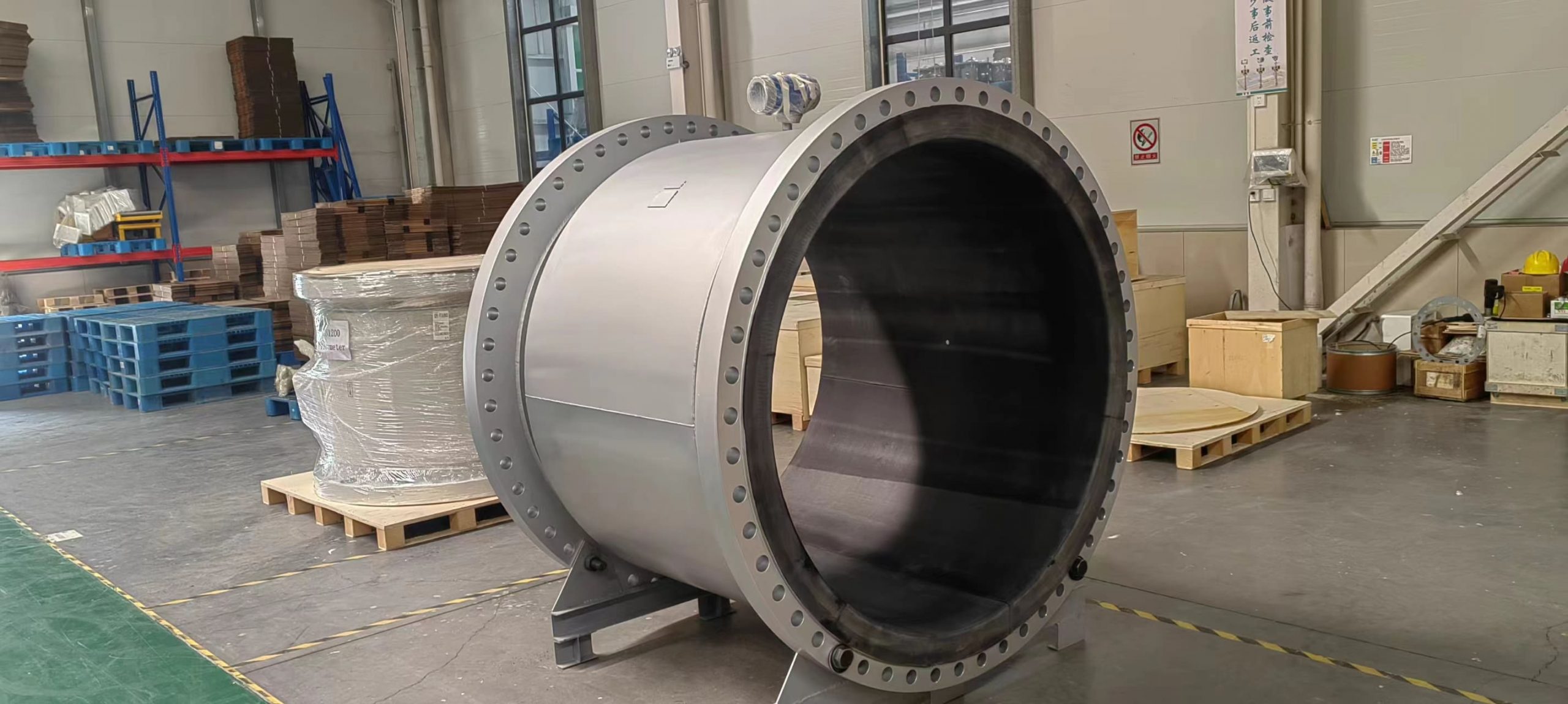
Installation of electromagnetic flowmeter
To ensure the measurement accuracy of the electromagnetic flowmeter, the correct installation is very important.
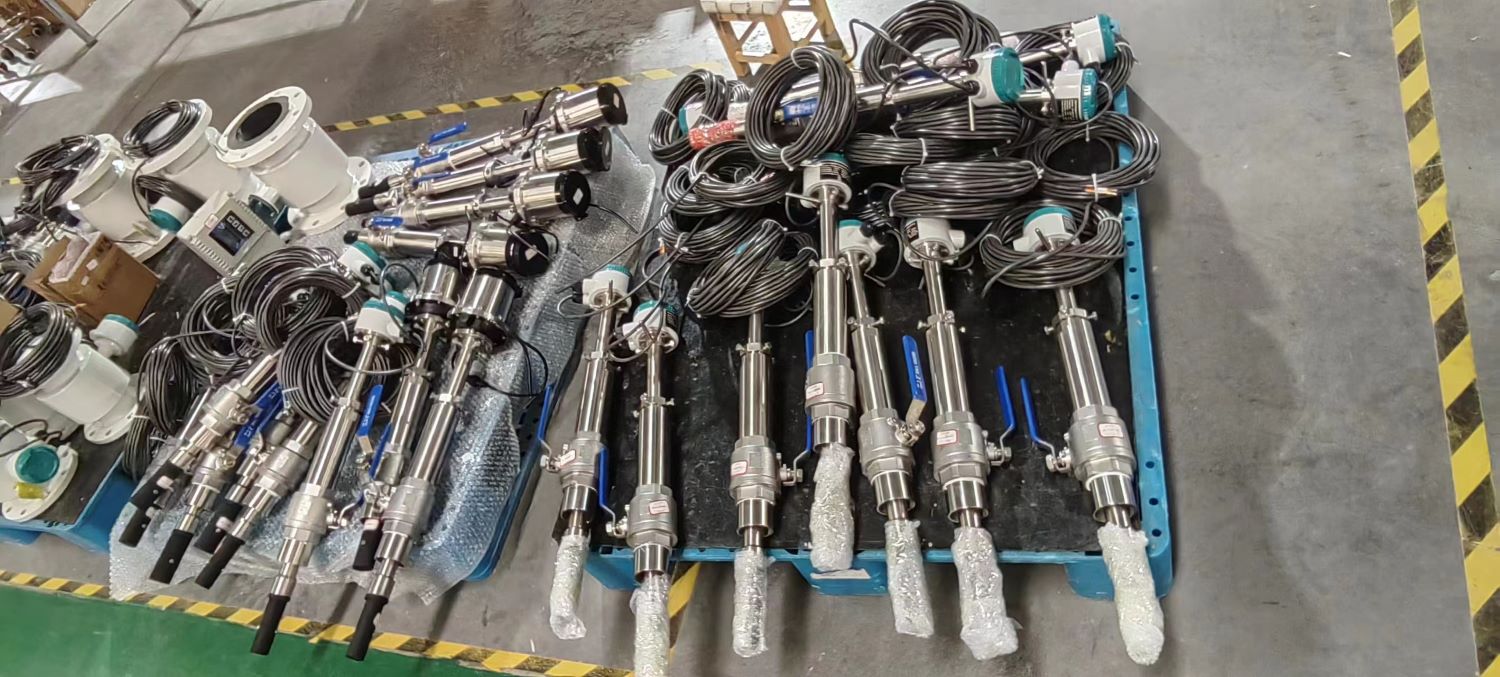
a. The transmitter should be installed in a dry and ventilated place indoors. Avoid installation in places where the ambient temperature is too high, should not be subject to strong vibration, and try to avoid equipment with strong magnetic fields, such as large motors, transformers, etc. Do not install in an area with corrosive gases. Installation location for easy access. This is the environmental condition to ensure the normal operation of the transmitter.
b. In order to ensure that the measuring tube of the transmitter is filled with the measured medium, the converter is installed vertically and flows from bottom to bottom. Especially for liquid-solid two-phase flow, it must be installed vertically. If only horizontal installation is allowed on site, ensure that the two electrodes are in the same horizontal plane
c. Both ends of the transmitter should be equipped with valves and bypasses.
d. The AC potential measured by the electrode of the electromagnetic flow transmitter is a few millivolts, which is based on the liquid potential in the transmitter. In order to stabilize the liquid potential and maintain equal potential between the transmitter and the fluid to ensure stable measurement, the transmitter housing and the metal tube should be well grounded, and the converter housing should also be grounded. The ground resistance cannot be greater than 10 and cannot be shared with the ground cables of other electrical devices. If good contact between the transmitter housing and the metal pipe cannot be guaranteed, metal wires should be used to connect them. Reliable grounding.
e. In order to avoid interfering with the signal, the signal between the transmitter and the converter must be transmitted by a shielded wire. It is not allowed to place the signal cable and the power cable parallel in the same cable steel pipe. Generally, the length of signal cable should not exceed 30 m.
f. The installation site of the converter should avoid AC, DC strong magnetic field and vibration, the ambient temperature is -20 to 50℃, does not contain corrosive gases, and the relative humidity is not more than 80%.
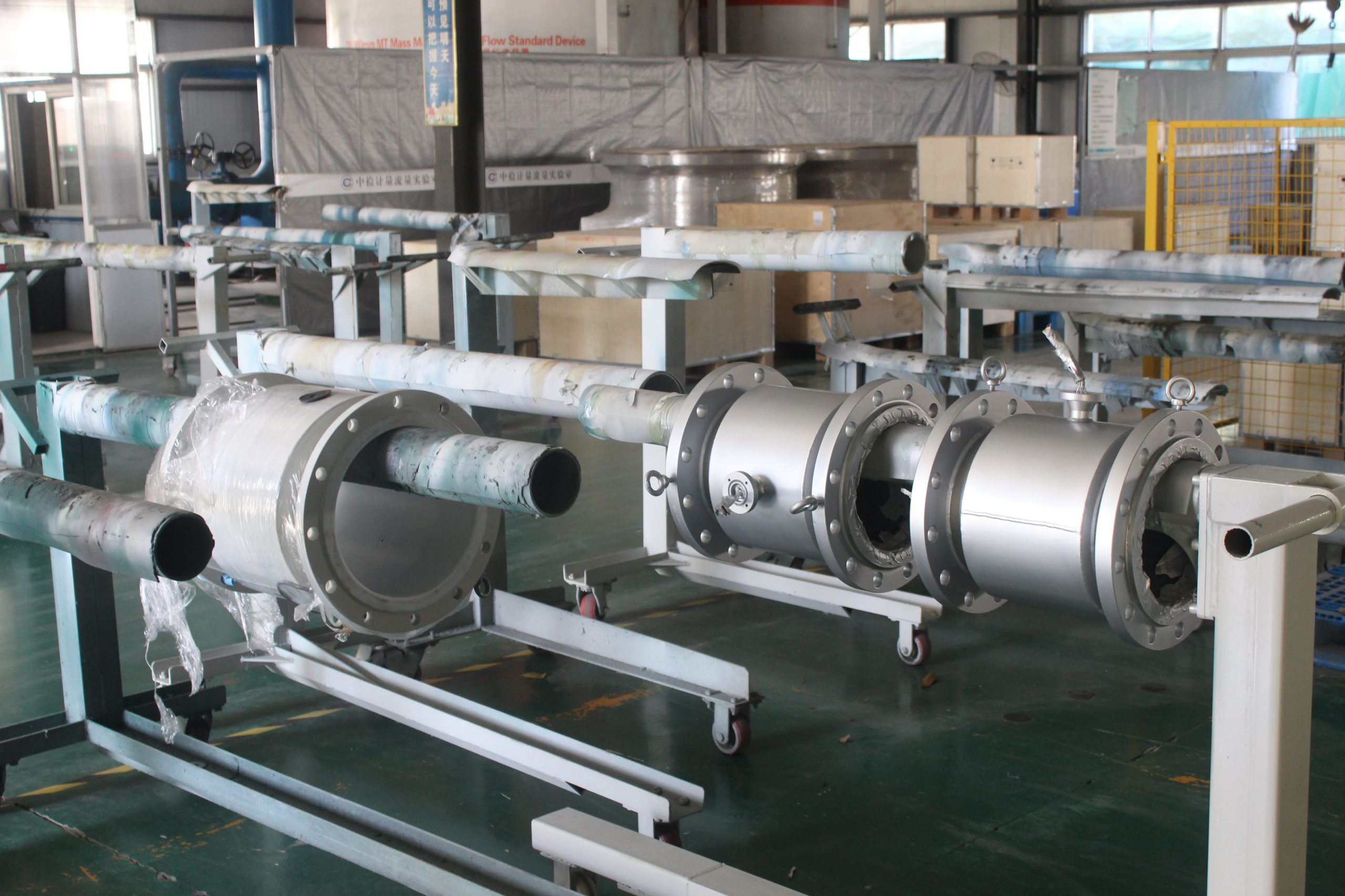
g. In order to avoid the influence of the relative measurement of the flow rate, the flow regulator should be set downstream of the transmitter. For small diameter transmitters, because the distance from the center of the electrode to the inlet end of the flow meter is equivalent to several times the length of diameter D, the upstream straight pipe can not be specified. However, for large diameter flowmeters, generally the upstream should have a straight pipe section of more than 5D, and the downstream generally does not require a straight pipe section.

-.jpg)