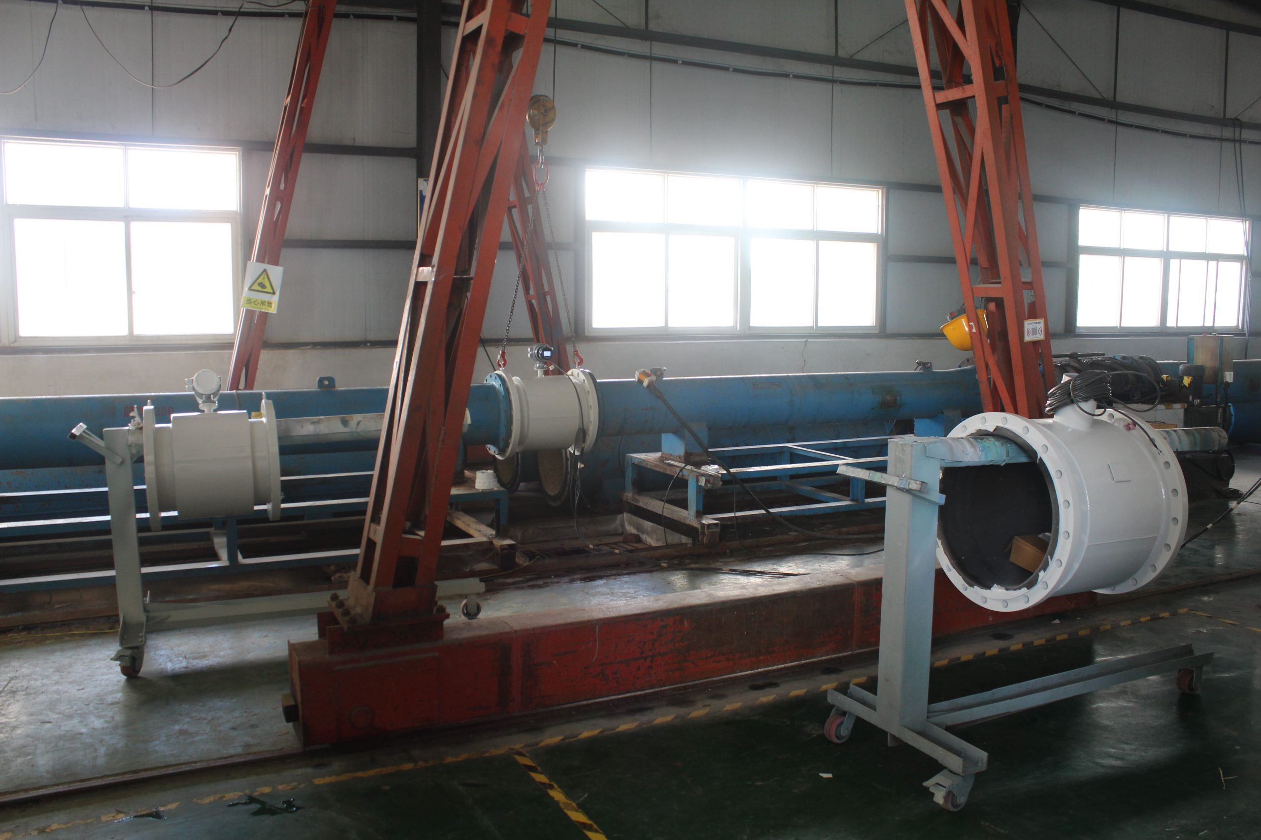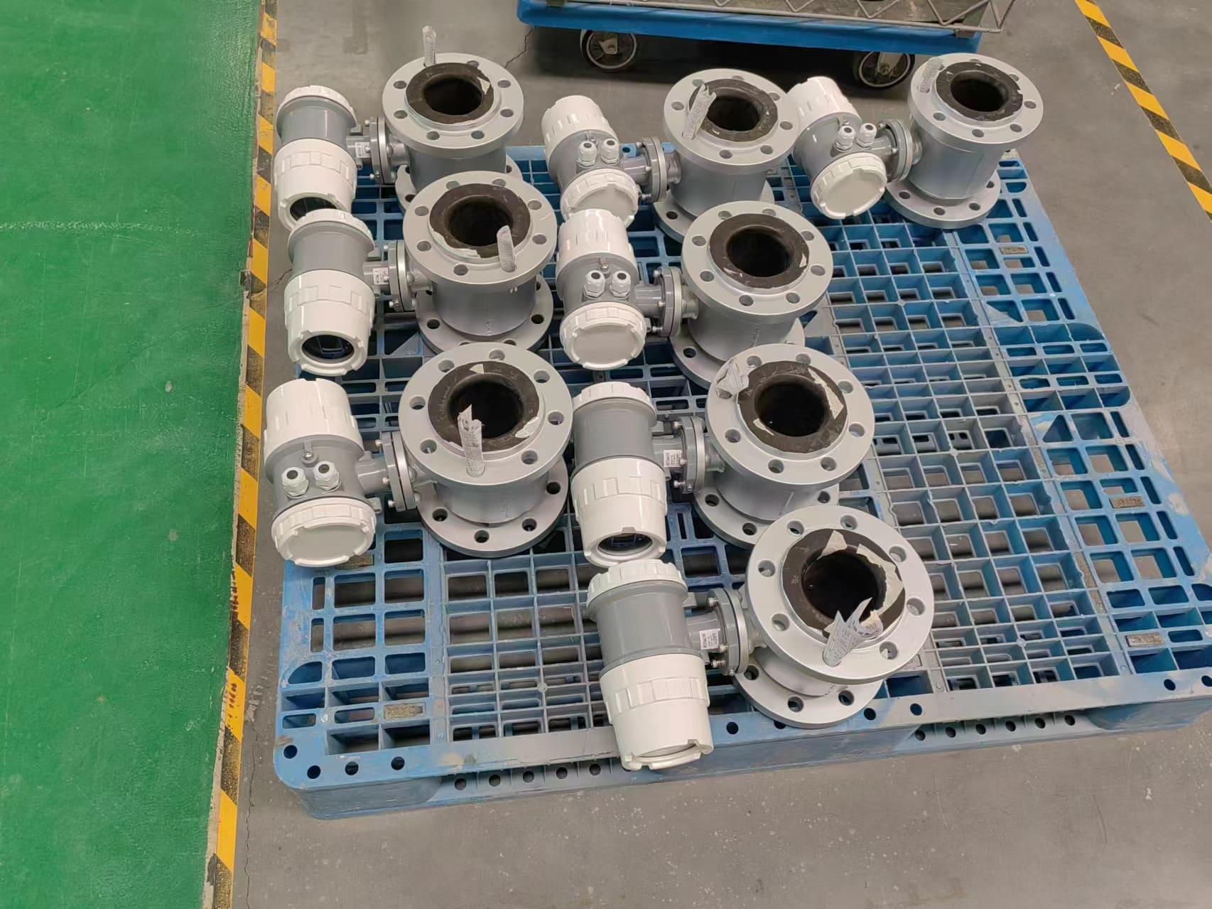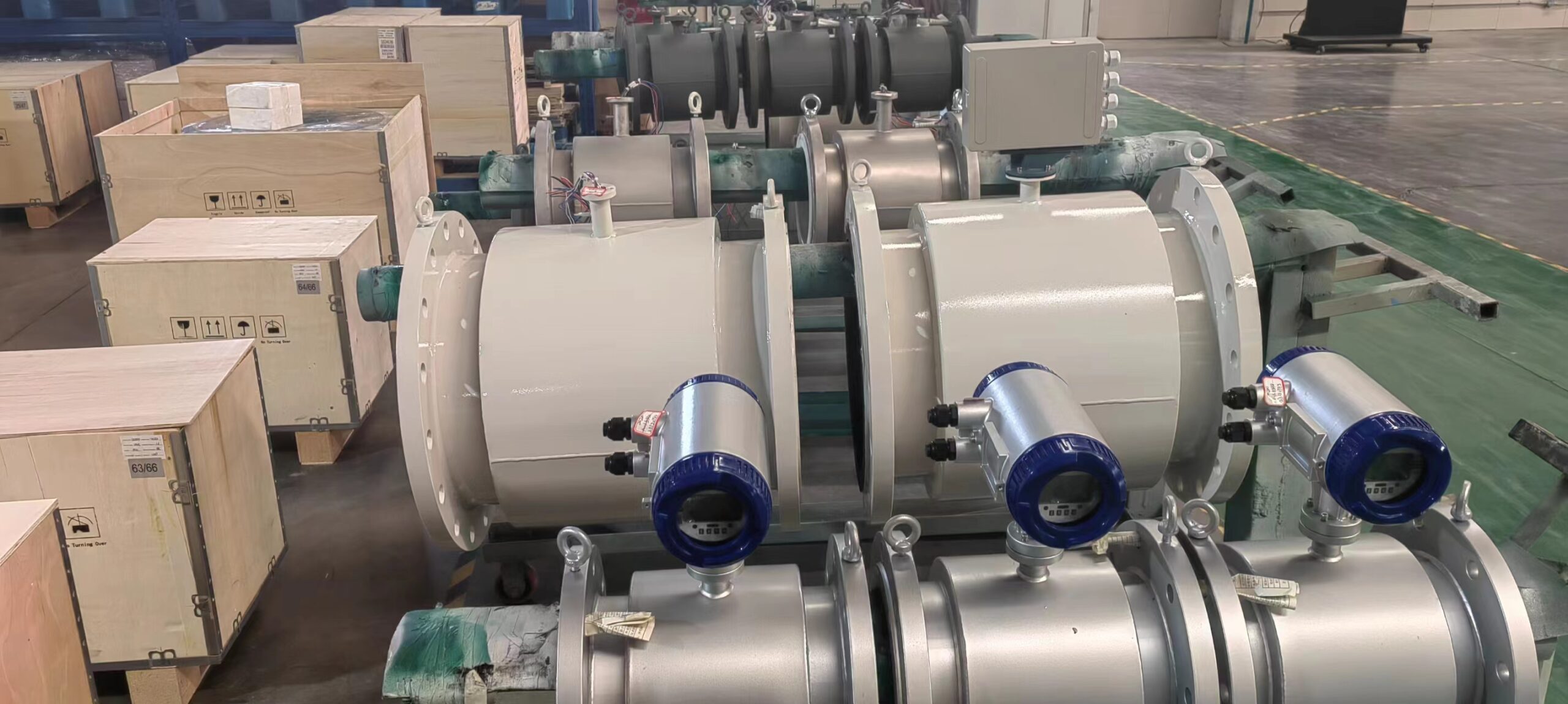
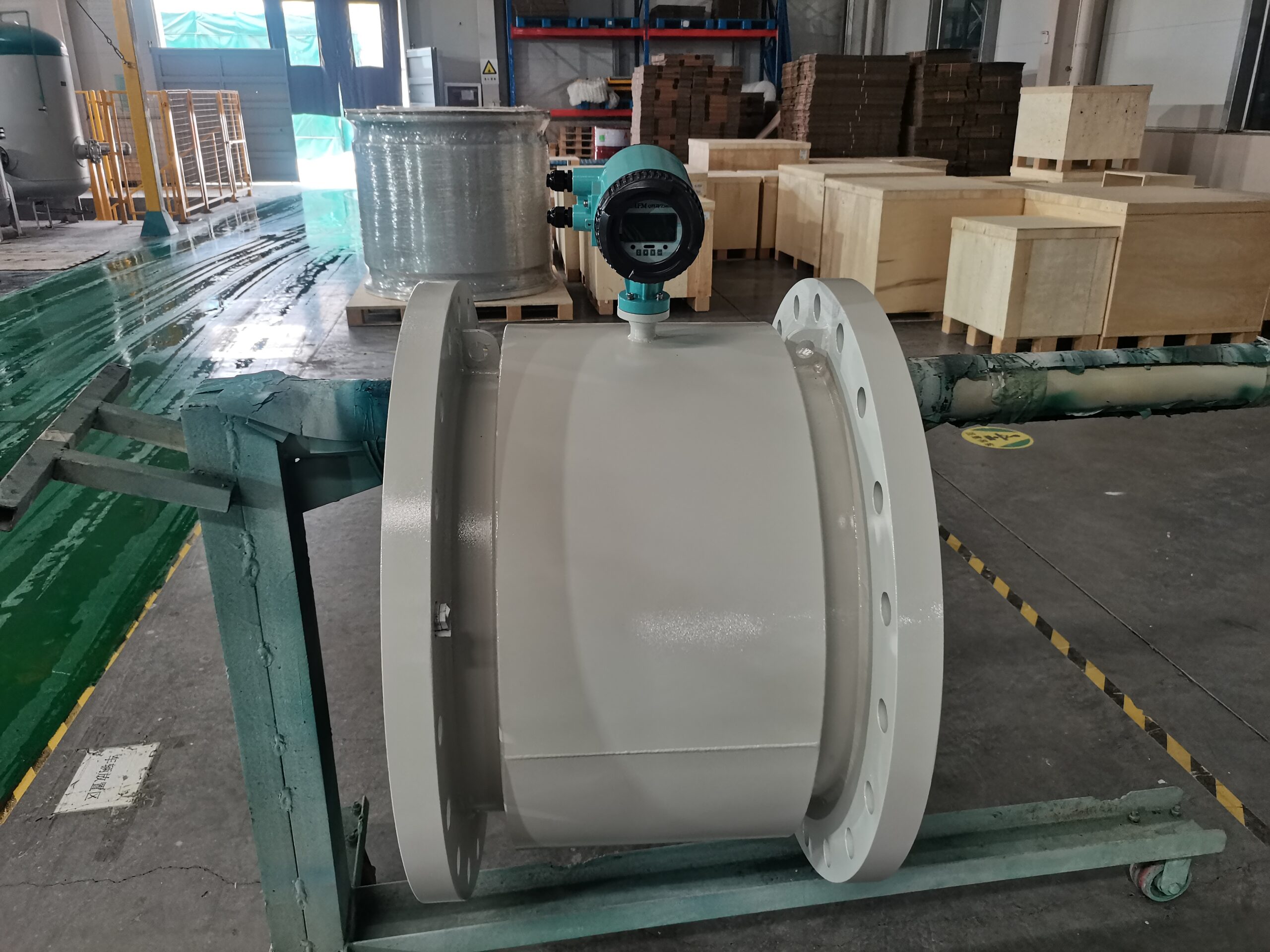
Common faults in the operation of split electromagnetic flowmeter
After the initial debugging and normal operation for a period of time, the split electromagnetic flowmeter fails in the operation process, the common causes of failure are: the internal flow sensor connection layer, lightning strikes, environmental changes. Below, the staff of the flowmeter manufacturer will lead you to understand some common faults of the split electromagnetic flowmeter.
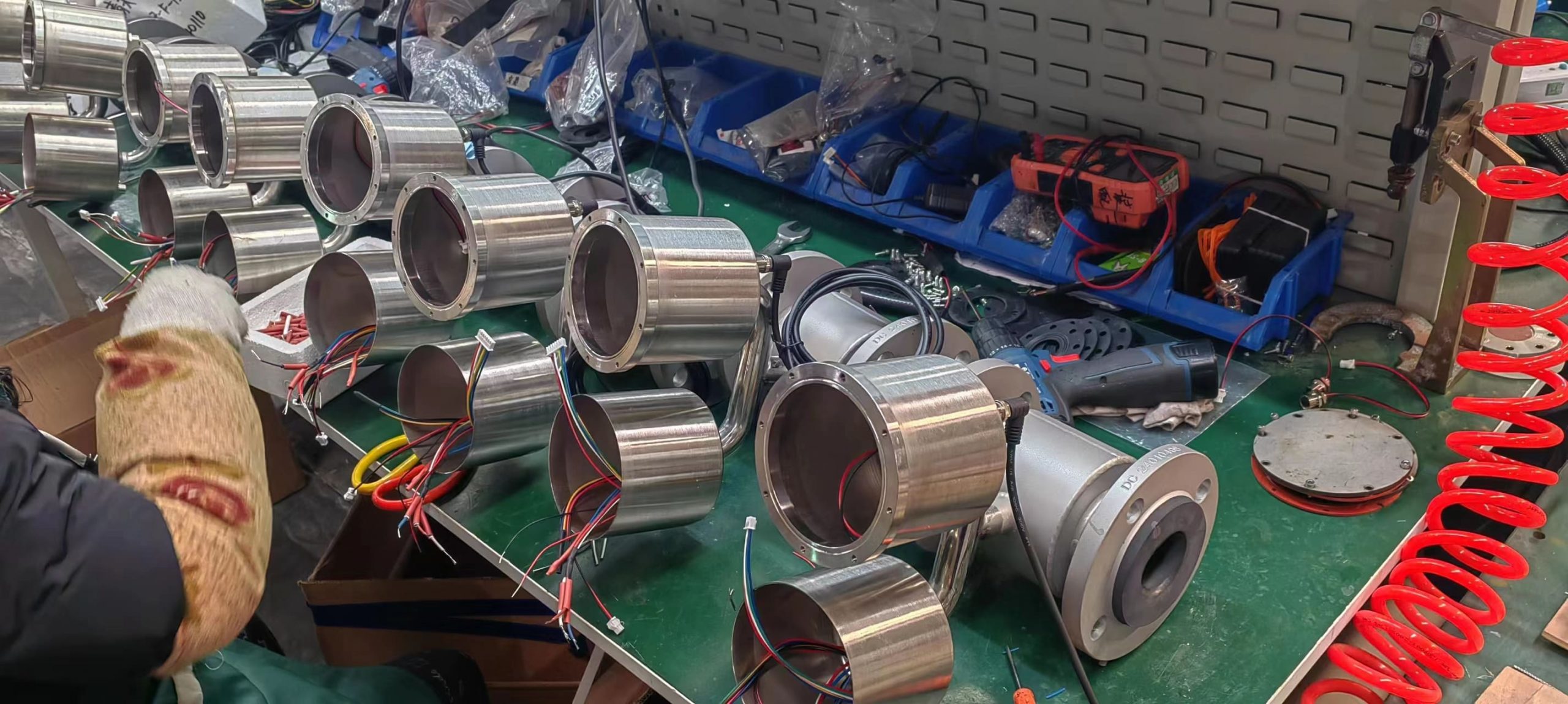
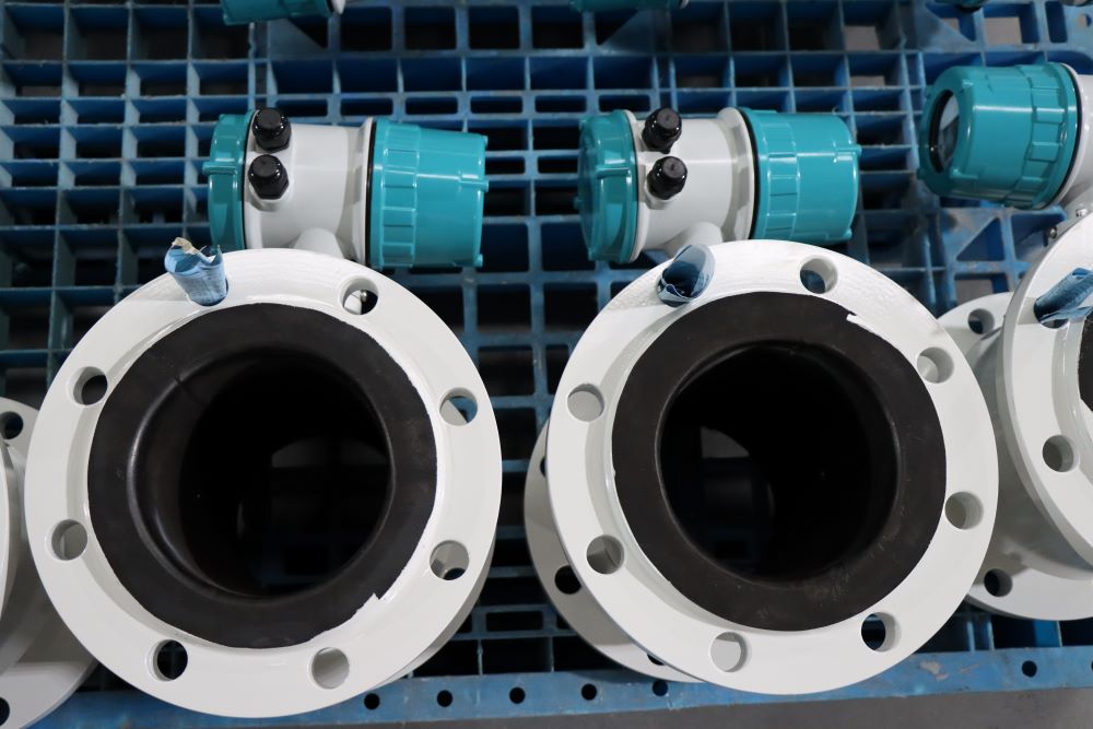
1. Internal connection layer
Flowmeter manufacturers realize that because split electromagnetic flowmeters measure more suspended solids or internal dirt than any other flow meter, inner connections occur with a higher failure efficiency. If the electrical conductivity and liquid conductivity adhesion layer is tight, the instrument can also output a normal signal, but changes the flow field, forming a hidden fault of measurement error; If the high conductivity adhesion layer, the electromotive force between the electrodes will short circuit; If the insulating layer is connected, the electrode surface insulates and disconnects the circuit. Both phenomena can cause the instrument to fail to work.
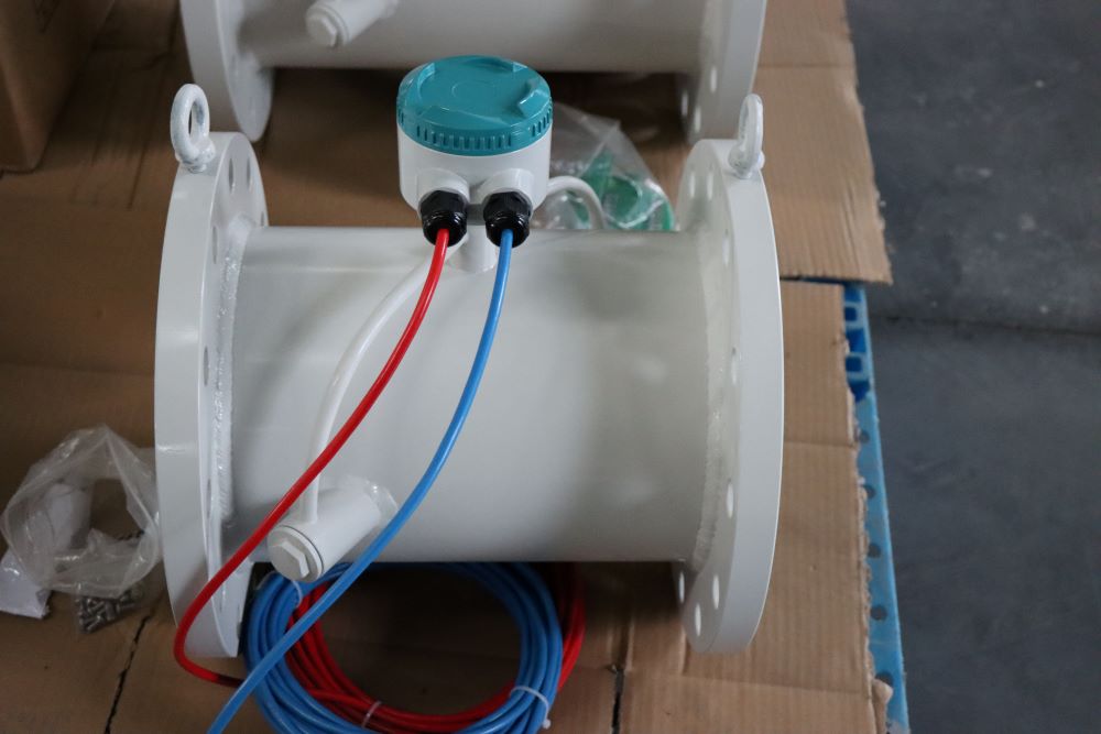
2. Lightning strikes
Internal electrical hits the circuit with high voltage induced transient surge current, which may damage the instrument to the instrument. Lightning strikes damage the instrument in three ways: the power cord, the sensor spoon converter between the excitation signal and the flow line. However, failure of various components from lightning damage is analyzed, resulting in failure of high voltage and surge current from the control room of the power supply circuit in other ways. Lightning strikes from the accident site split electromagnetic flowmeter, not only failed, control room, in other instruments electrical often occur at the same time lightning accidents. Therefore, the user knows the importance of power line control room instrumentation, lightning protection facilities. If the current general and exploratory design unit team exists to solve this problem.
3. Changes in environmental conditions
During the debugging phase, the fault environment is not only interfered with during the operation of the interference source during the debugging, for example, grounding fault protection is not ideal, split electromagnetic flowmeter, no air source plant and equipment work normally during debugging, but during the operation, new interference sources (such as point tubes or near and far tube welding implementation) interfere with the normal operation of the instrument. There are large fluctuations in the output signal.
-.jpg)