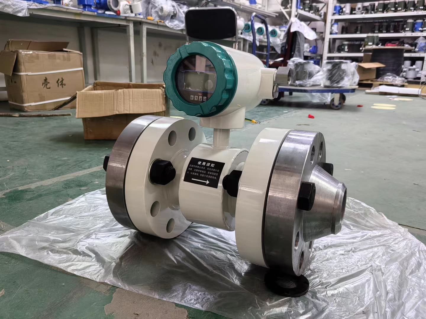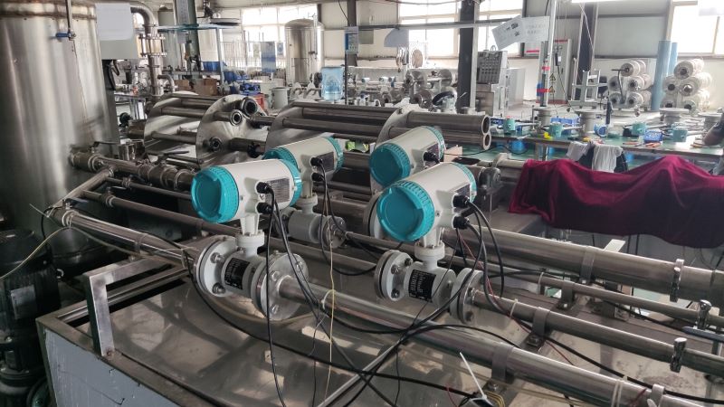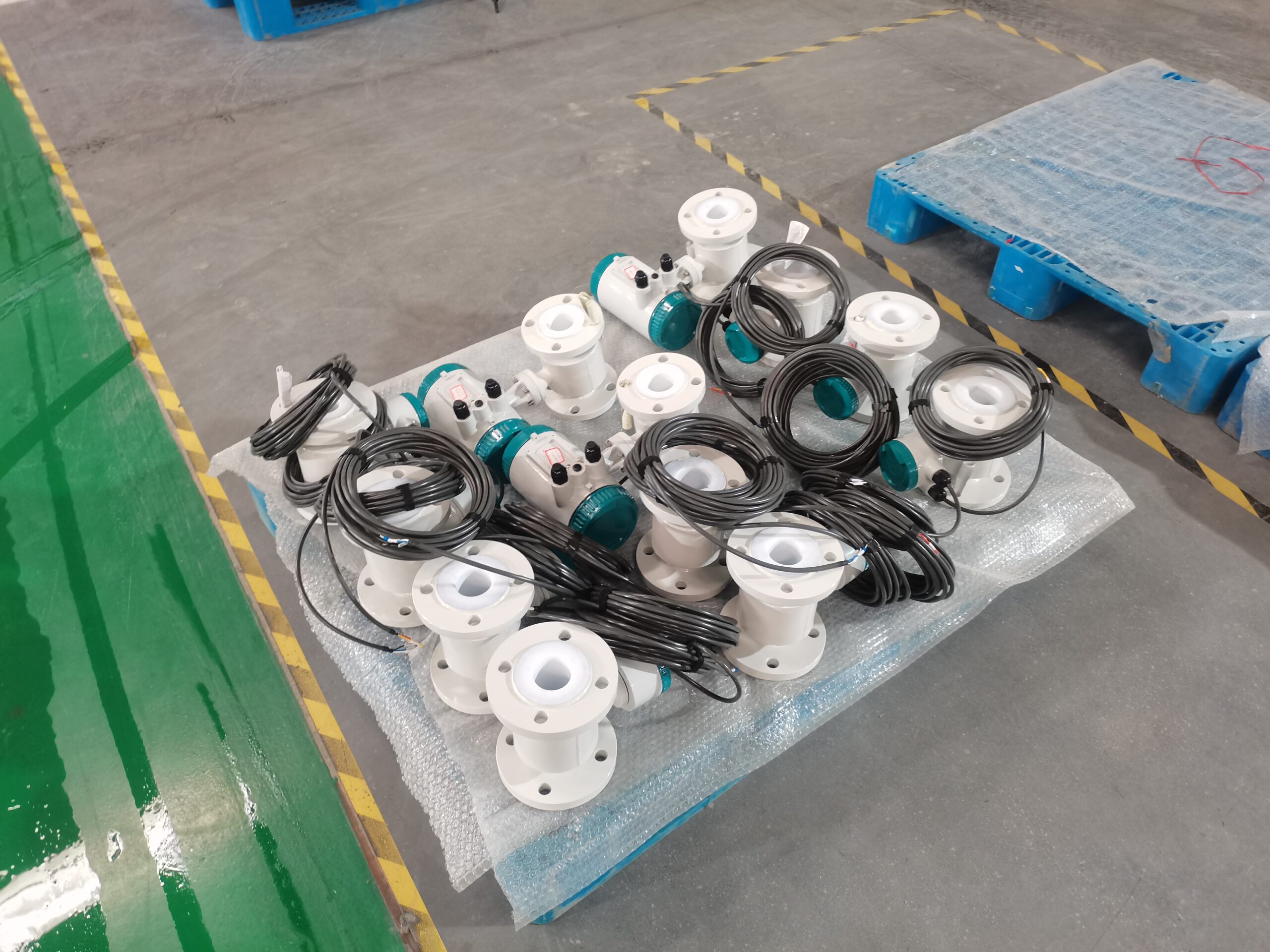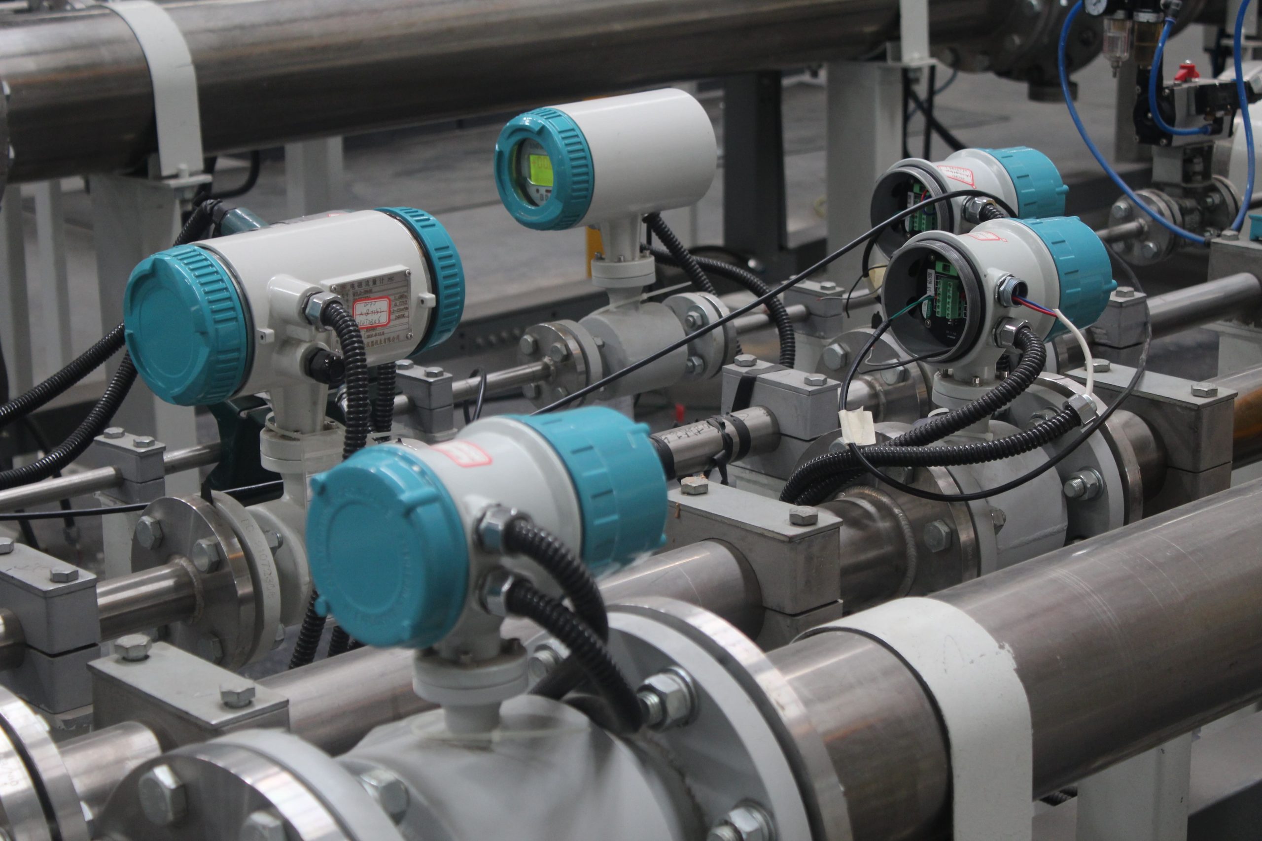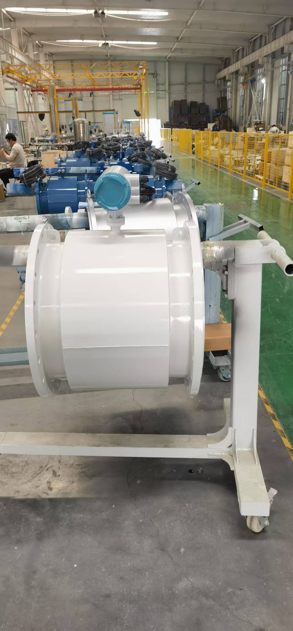
The structural mode of the electromagnetic flowmeter
The structure of an electromagnetic flowmeter mainly consists of multiple key components, which work together to measure the flow of conductive liquids. The following are the main structural components and functions of the electromagnetic flowmeter:
1. Magnetic circuit system
Function: Generate uniform direct current or alternating current magnetic fields. Direct current magnetic circuits are usually implemented using magnets, with a relatively simple structure and less interference from alternating current magnetic fields. However, the direct current magnetic field is prone to polarizing the electrolyte liquid passing through the measuring conduit, affecting the measurement accuracy. Therefore, electromagnetic flowmeters mostly adopt alternating magnetic fields, which are usually generated by a 50HZ industrial frequency power supply.
Features: The alternating magnetic field can prevent electrode polarization, improve measurement accuracy, and meet the requirements of different pipe diameters at the same time.
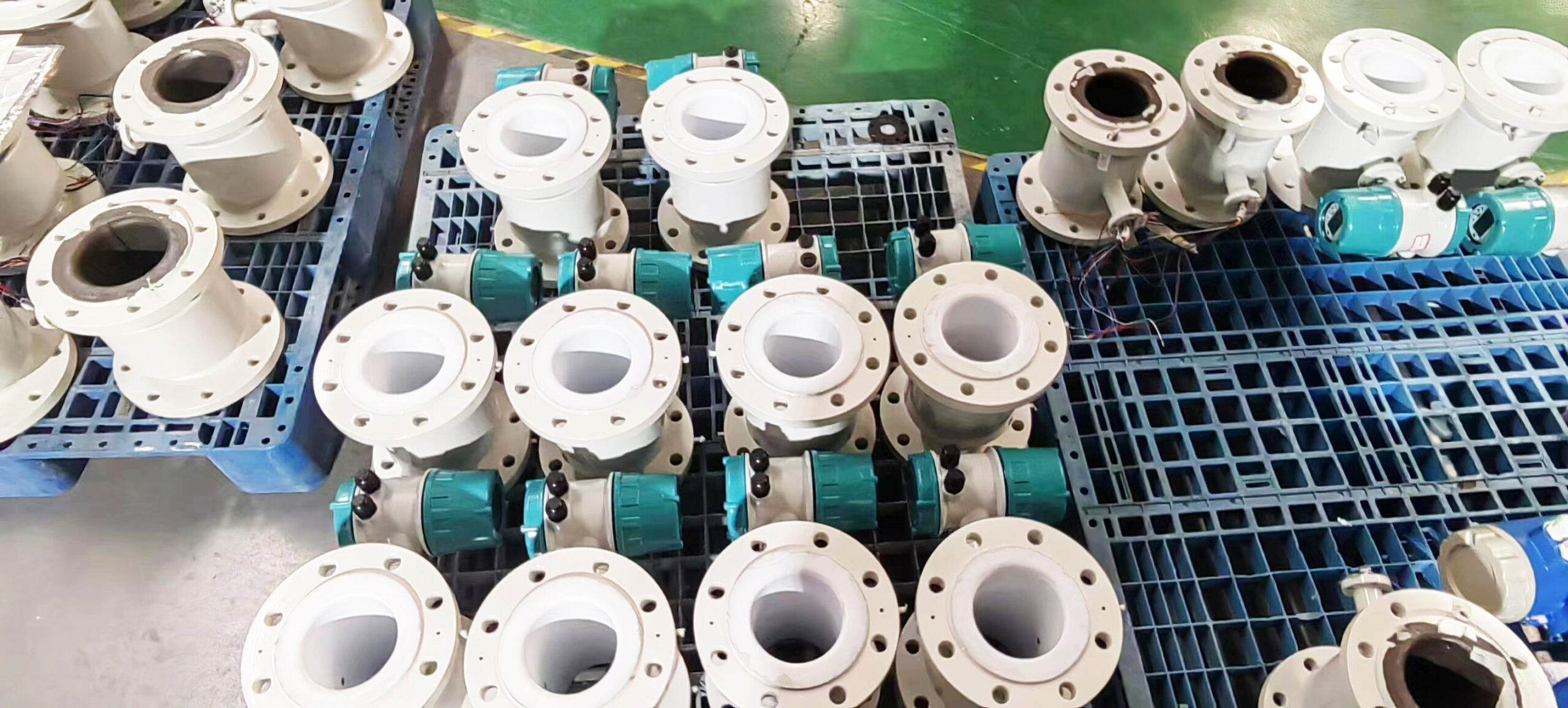
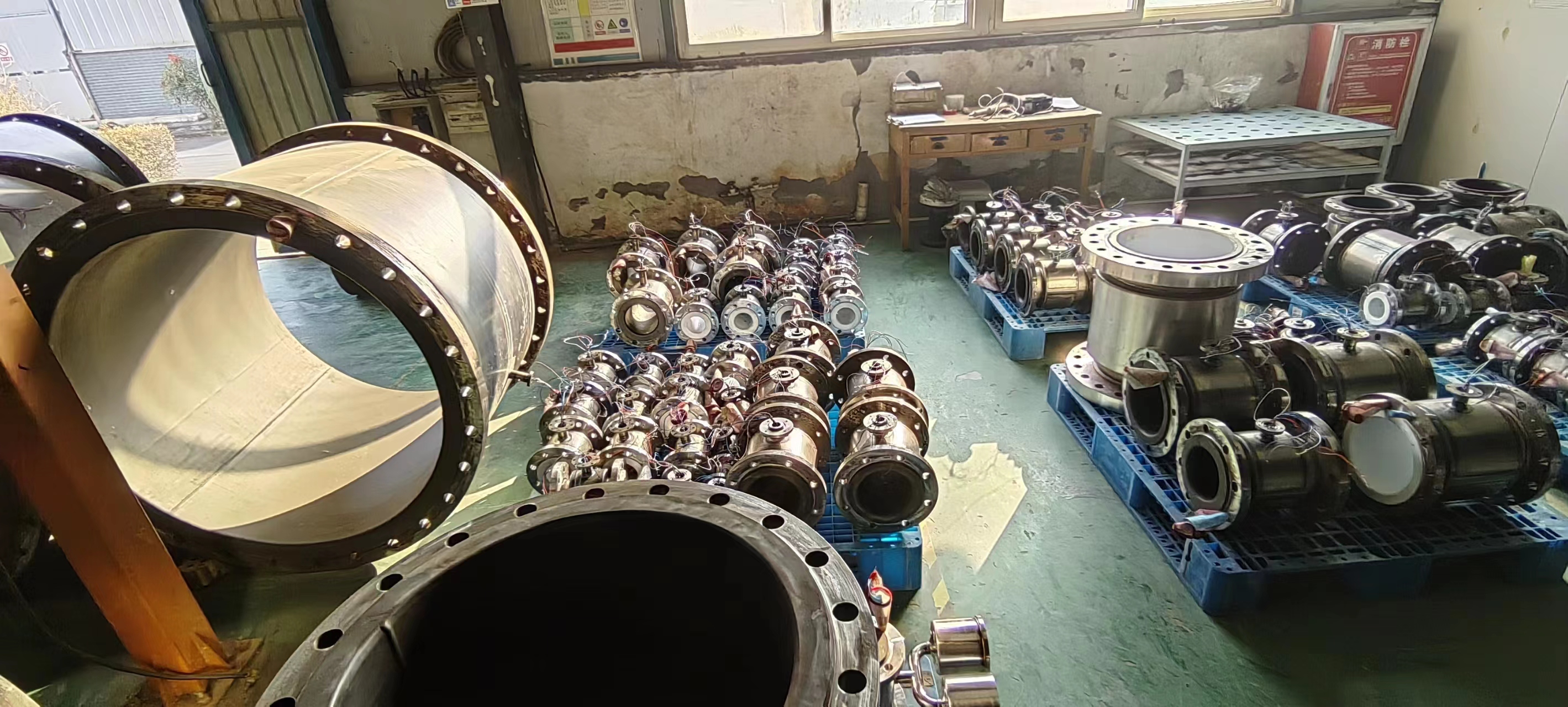
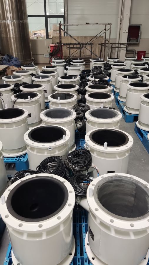
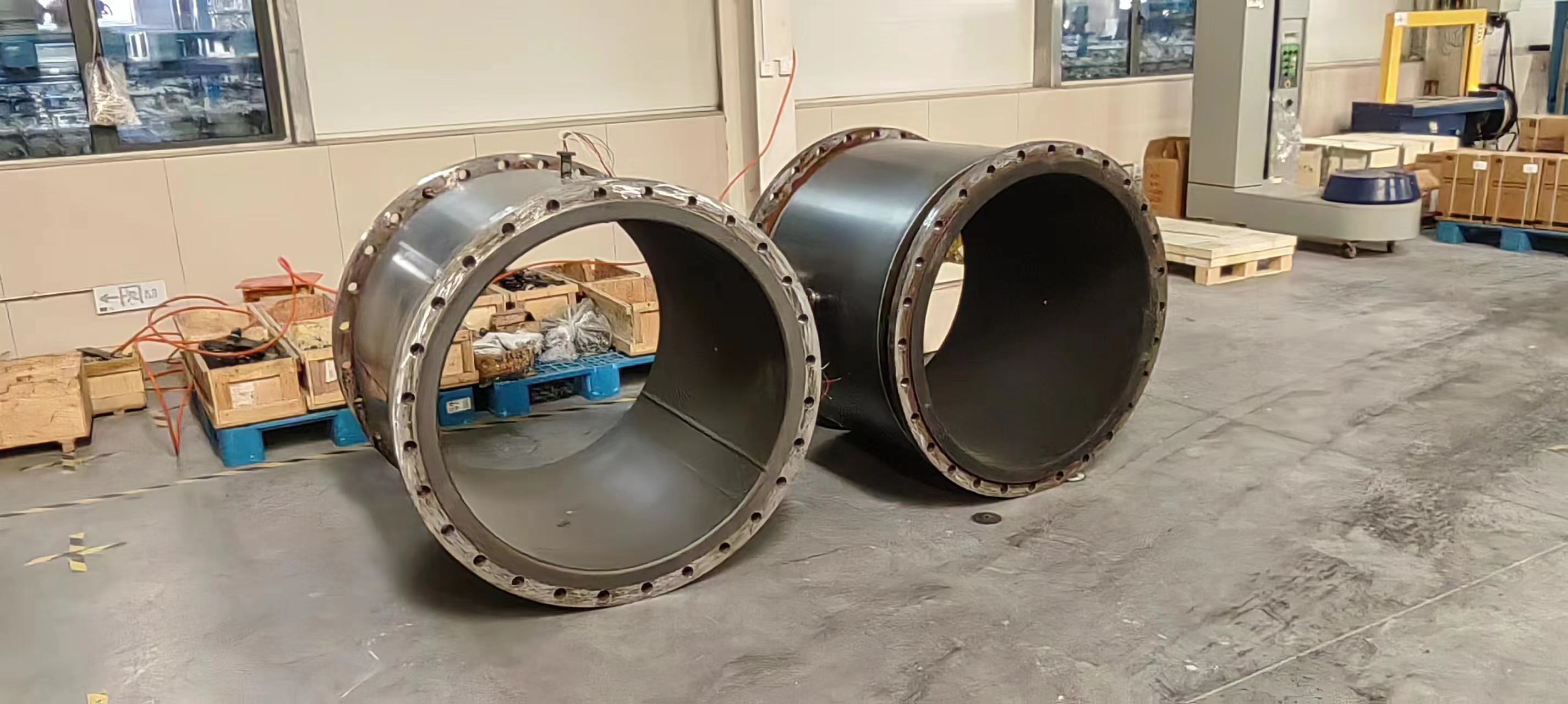
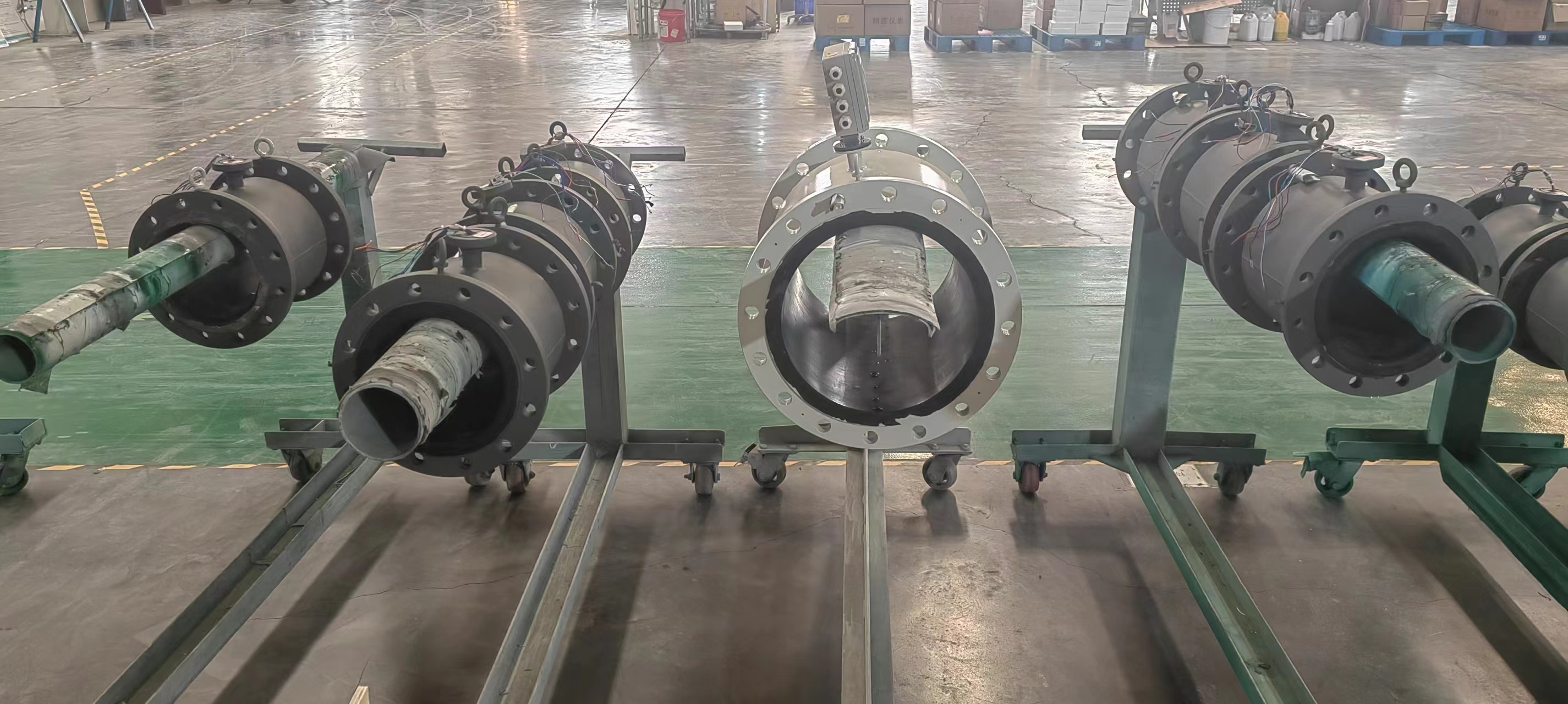
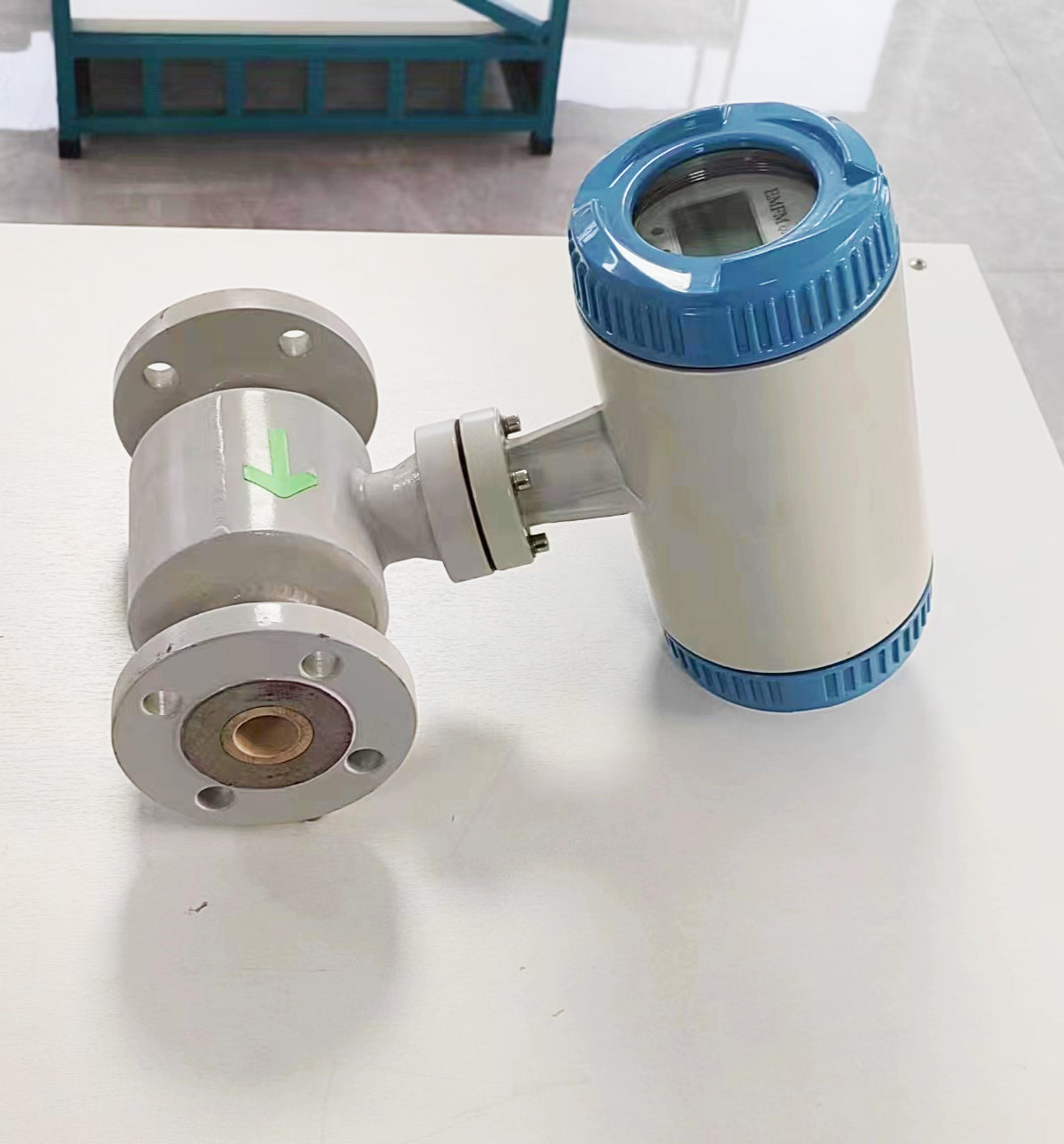
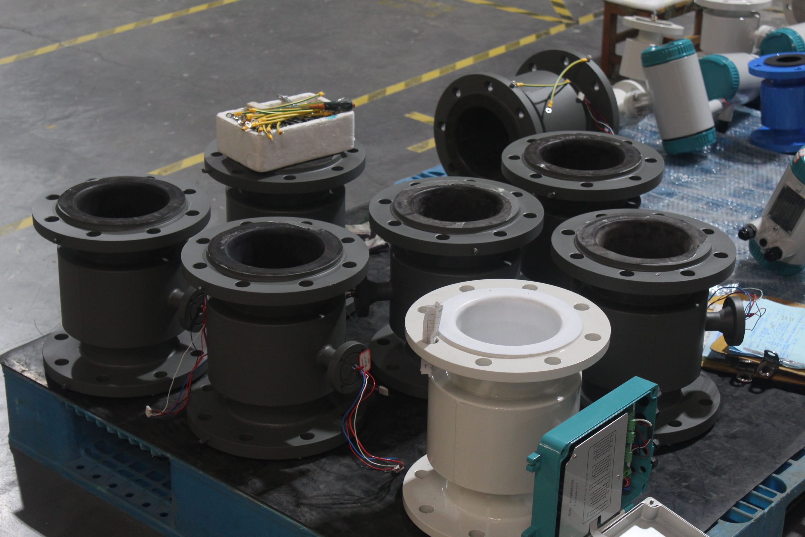
2. Measuring conduit
Function: As a pipe for the flow of conductive liquids under test. The measuring conduit must be made of materials that are non-magnetic, have low electrical conductivity, low thermal conductivity and certain mechanical strength, such as stainless steel, fiberglass reinforced plastic, high-strength plastic, etc.
Feature: Ensures that the magnetic flux is not diverted or short-circuited when the magnetic field lines pass through the measuring conduit, guaranteeing measurement accuracy.
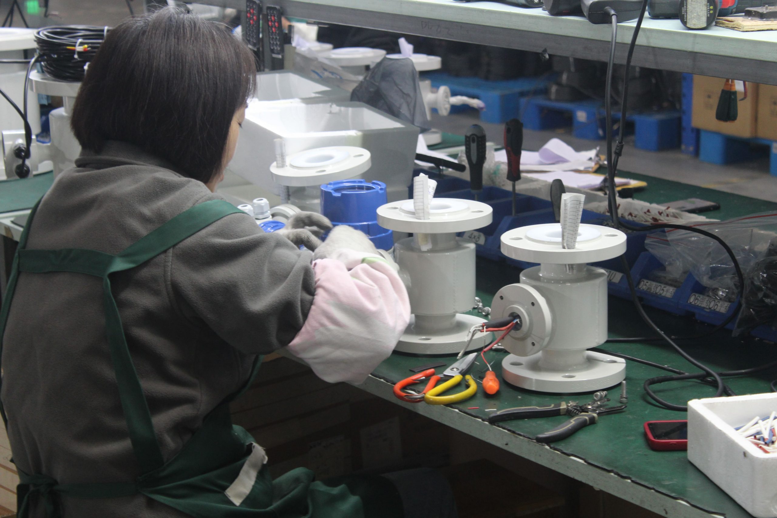
3. Electrode
Function: Extract the induced electromotive force signal proportional to the measurement. Electrodes are usually made of non-magnetic materials, such as stainless steel, and are flush with the lining to reduce fluid flow resistance.
Installation location: It is advisable to install it in the vertical direction of the pipeline to prevent the accumulation of sediment from affecting the measurement accuracy.
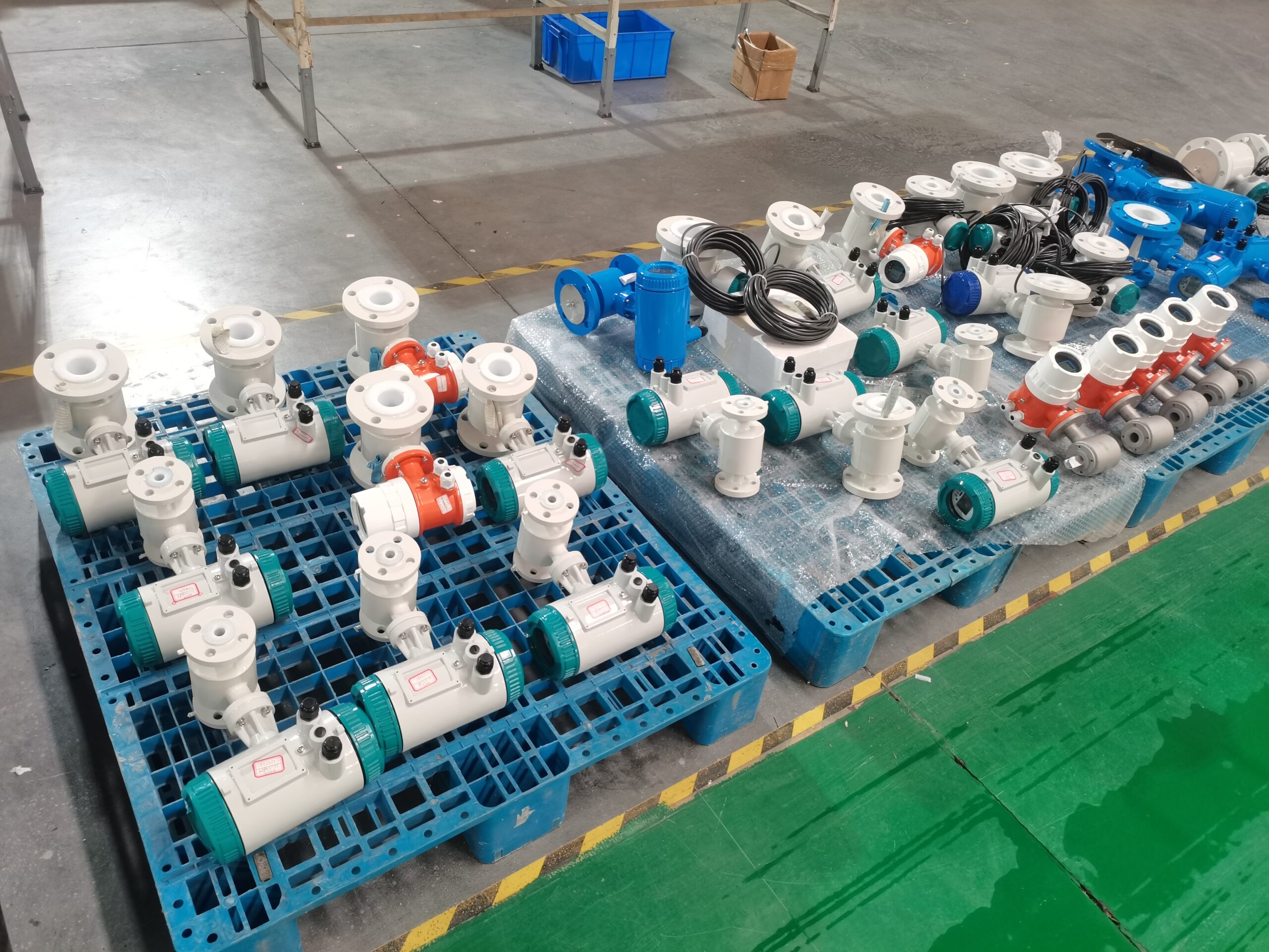
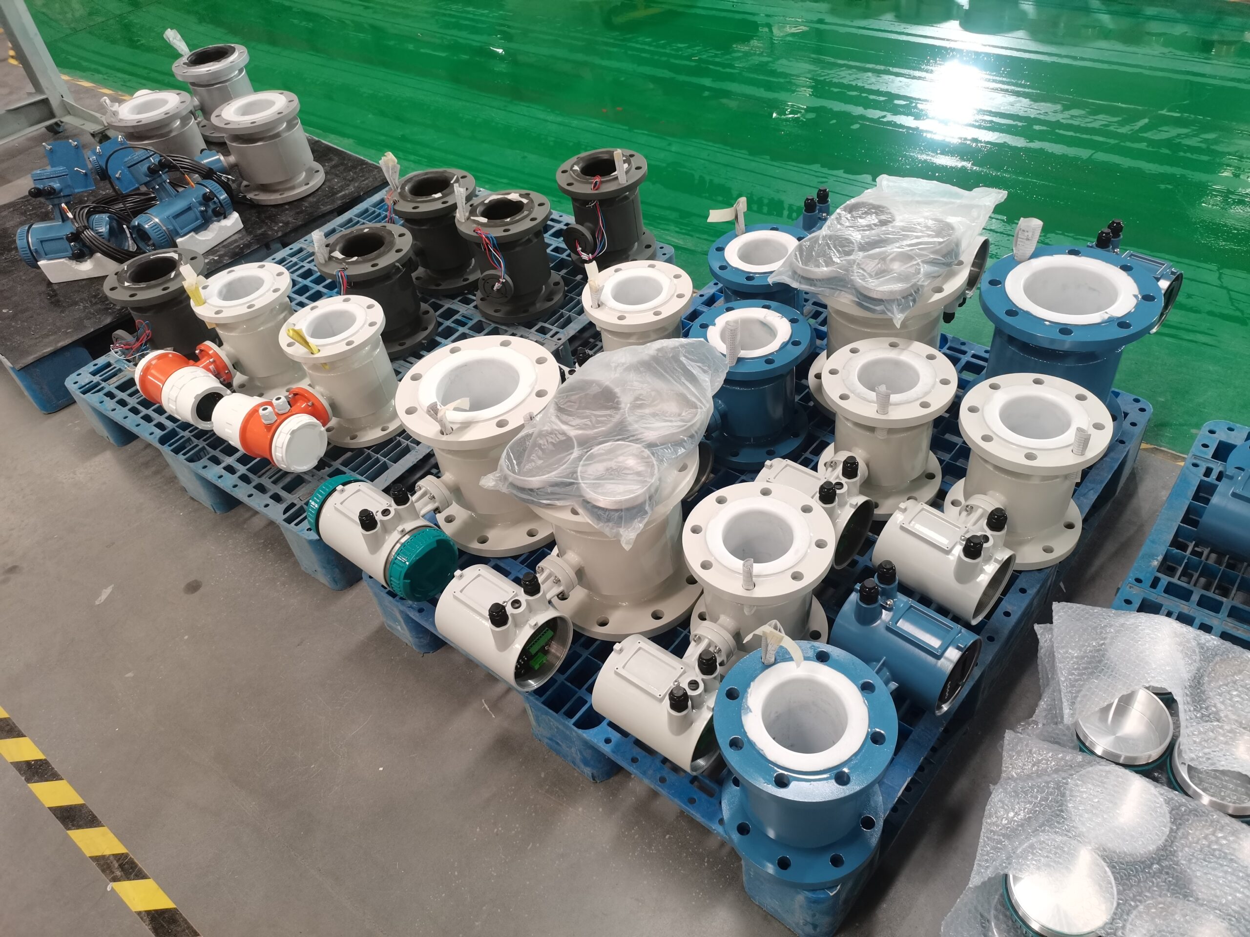
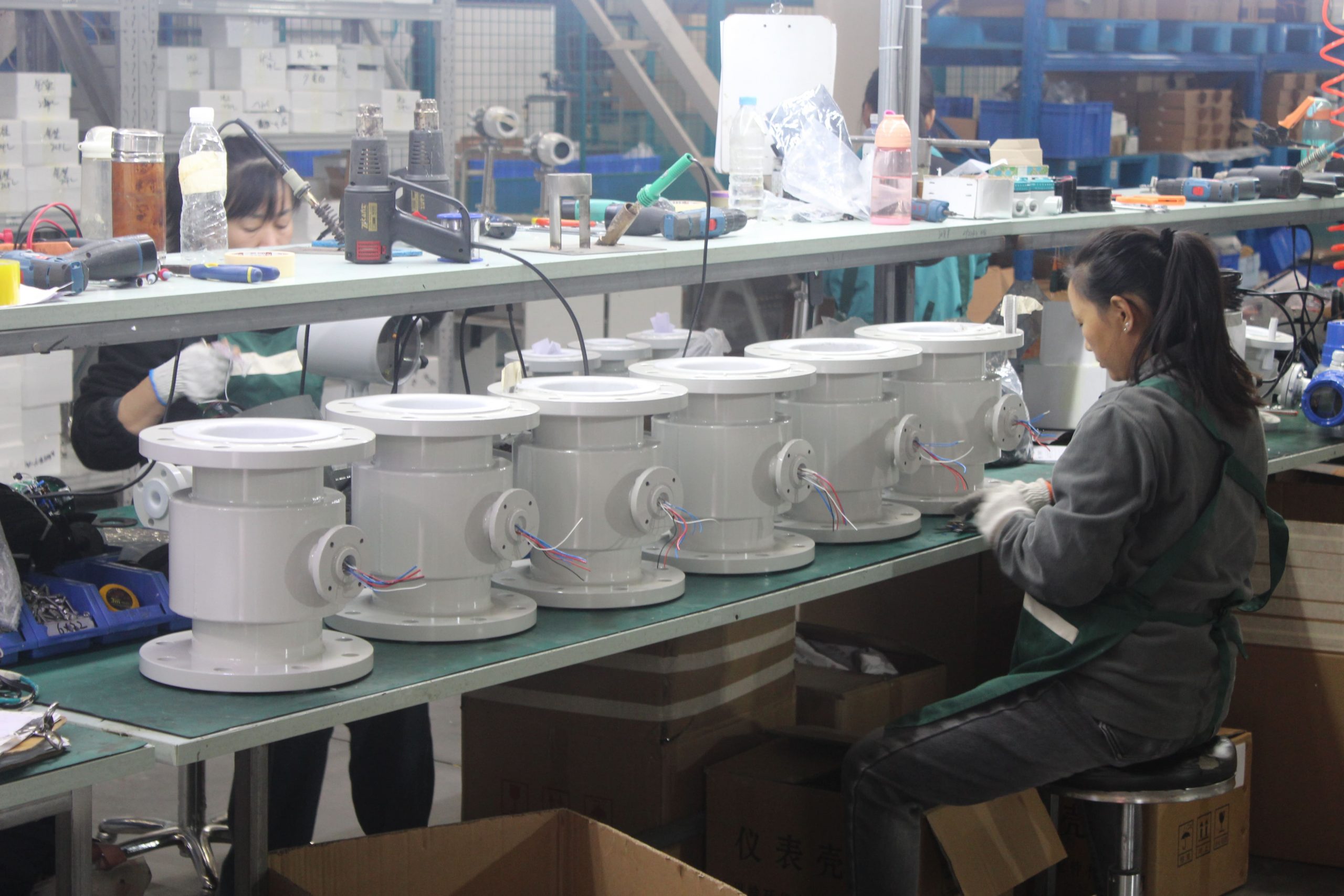
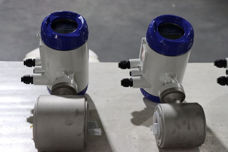
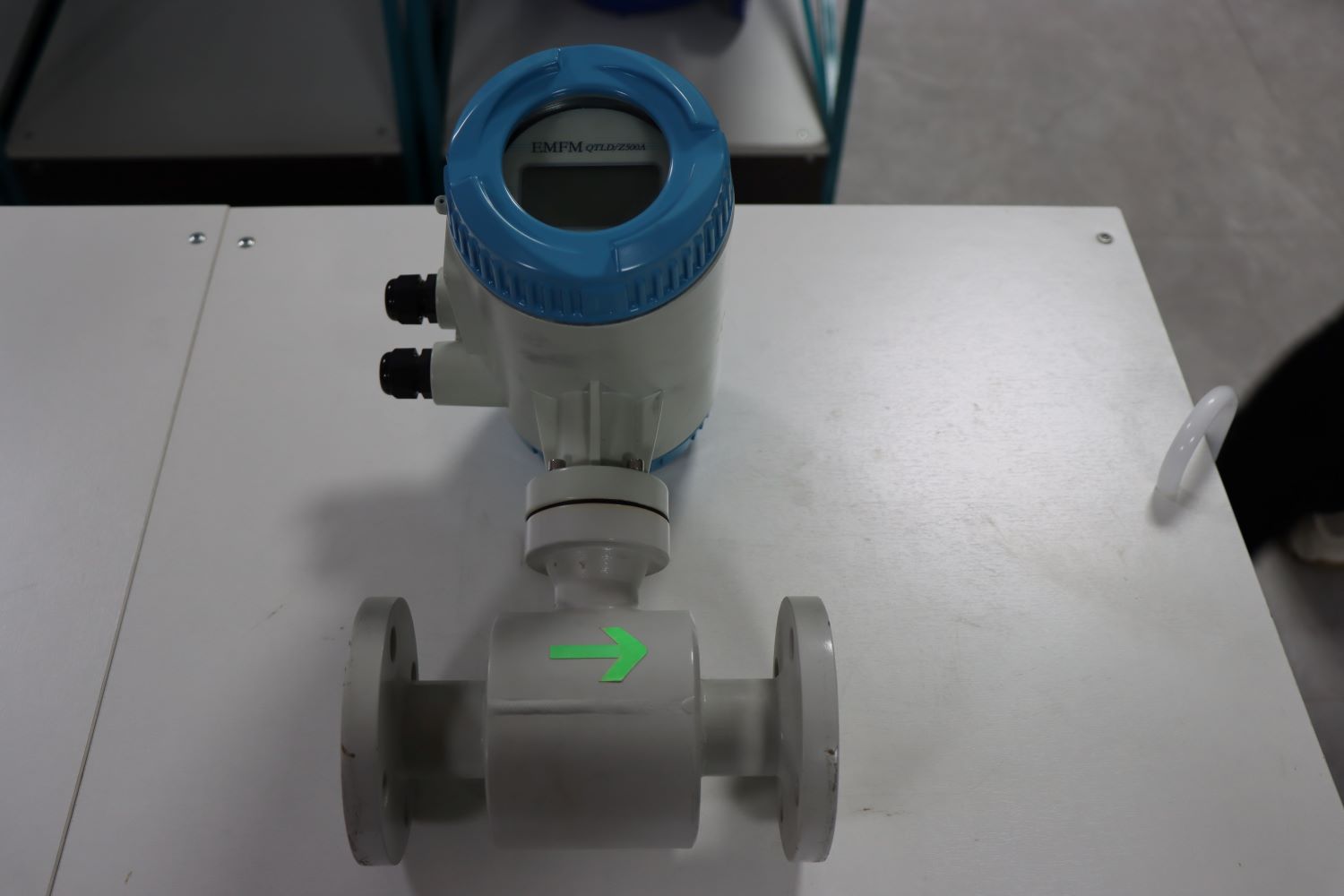
4. Shell
Function: Protect internal components and isolate external magnetic field interference. The shell is usually made of ferromagnetic material and serves as the outer cover for the excitation coil.
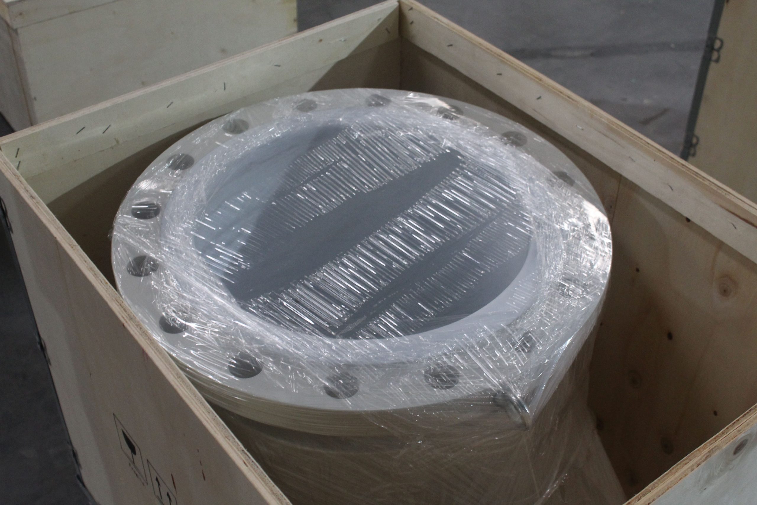
5. Lining
Function: To provide a complete electrically insulating lining on the inner side of the measuring conduit and the sealing surface of the flange. The lining materials are mostly corrosion-resistant, high-temperature resistant and wear-resistant polytetrafluoroethylene plastics, ceramics, etc. They come into direct contact with the measured liquid to enhance the corrosion resistance of the measuring conduit and prevent short circuits due to induced electromotive force.
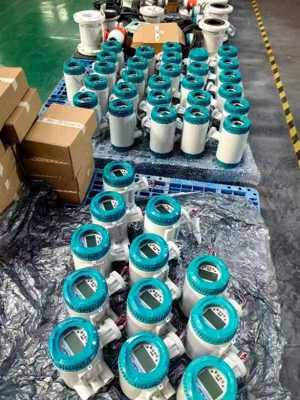
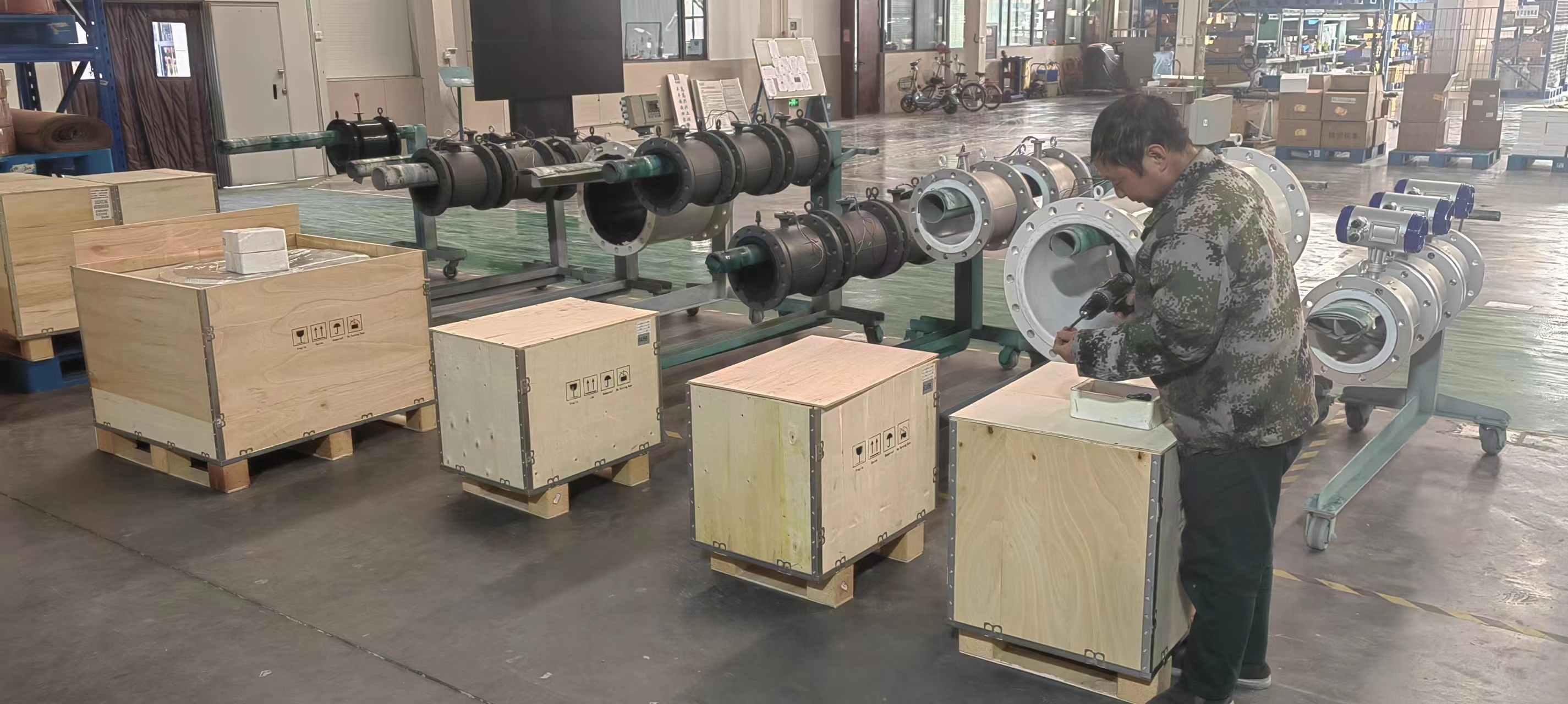
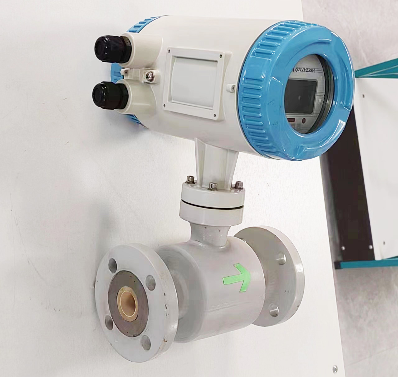
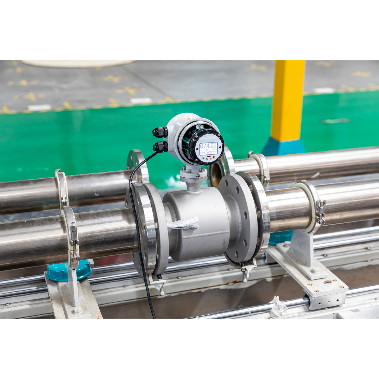
6. Converter
Function: Amplify the induced electromotive force signal and convert it into a unified standard signal (such as 4-20mA), while suppressing the main interference signal. The converter ensures the stability and accuracy of the signal, facilitating subsequent display, recording or control.
The structural design of the electromagnetic flowmeter is closely centered around its measurement principle. It achieves precise measurement of the flow of conductive liquids through key links such as generating a magnetic field through the magnetic circuit system, allowing conductive liquids to pass through the measuring conduit, extracting induced potential signals through electrodes, protecting internal components through the housing, enhancing corrosion resistance through the lining, and processing signals through the converter. This structural approach makes electromagnetic flowmeters have broad application prospects in industrial fields such as chemical engineering, water treatment, and metallurgy.
-.jpg)