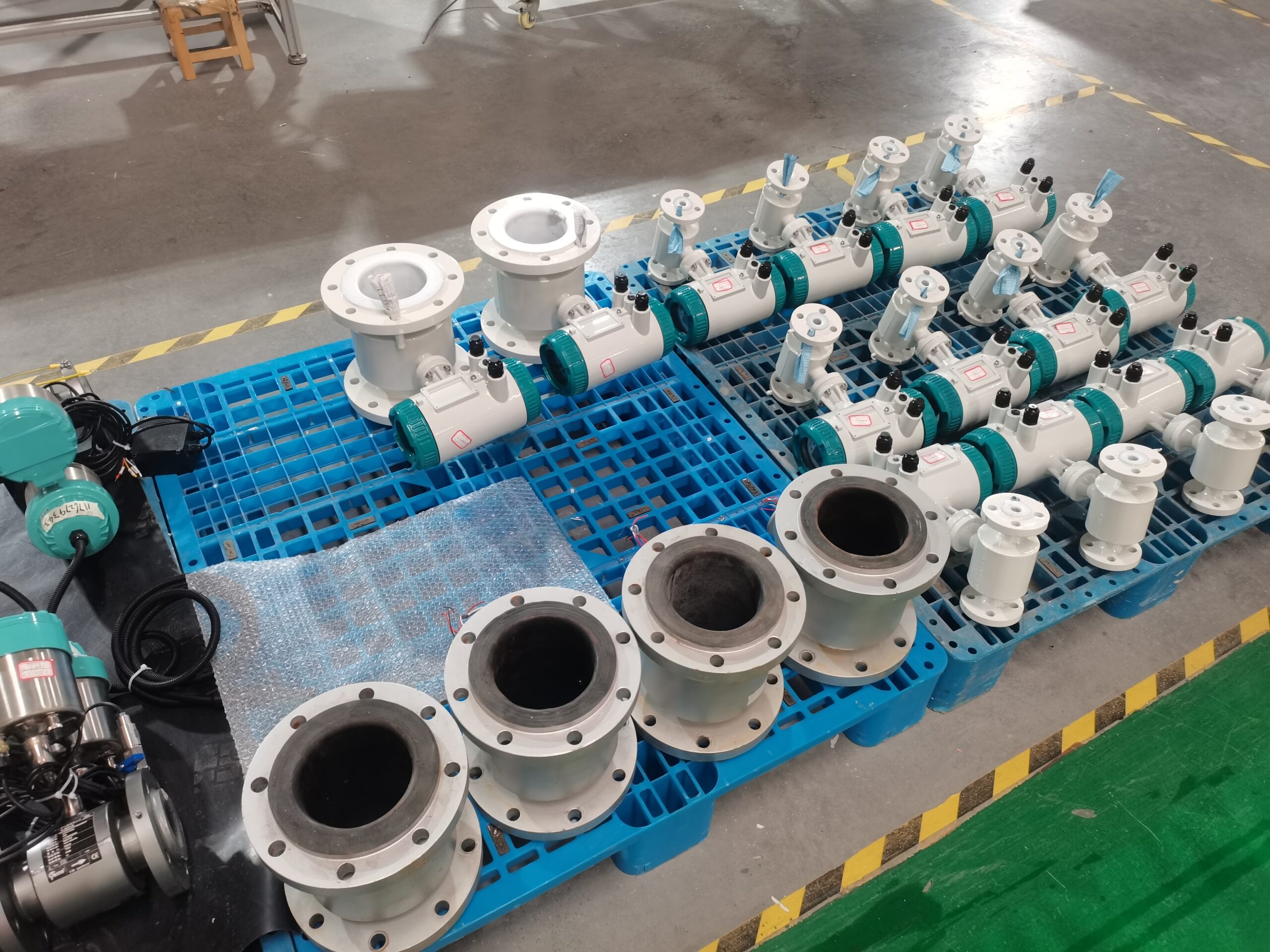
Standards for the installation and use of insertable electromagnetic flowmeters
The installation and usage standards and common precautions of insertable electromagnetic flowmeters: Accurate and error-free detection requires the selection of reasonable instruments. The product quality of the instrument is the key. Moreover, the installation and usage standards must be considered.
If the installation and usage are not standardized and regulated, the effect of the instrument cannot be effectively exerted. Therefore, we must attach great importance to the installation and usage of flowmeters. Next, let’s introduce to you the installation and usage standards as well as common precautions for insertable electromagnetic flowmeters
1. Insertable electromagnetic flowmeters should be appropriately kept away from dedicated equipment with strong electromagnetic fields.
2. The installation and usage site should not have strong vibration, the pipeline should be stable and reliable, and the ambient temperature should not fluctuate greatly.
3. The installation and usage location must ensure that the pipeline is always filled with the fluid to be measured. The length of the straight pipe section upstream of the pipeline where the sensor is installed and used should be greater than 8D, and the length of the straight pipe section downstream should not be less than 5D.
4. Thoroughly remove the welding slag and burrs from the installation and usage base of the pipe under test.
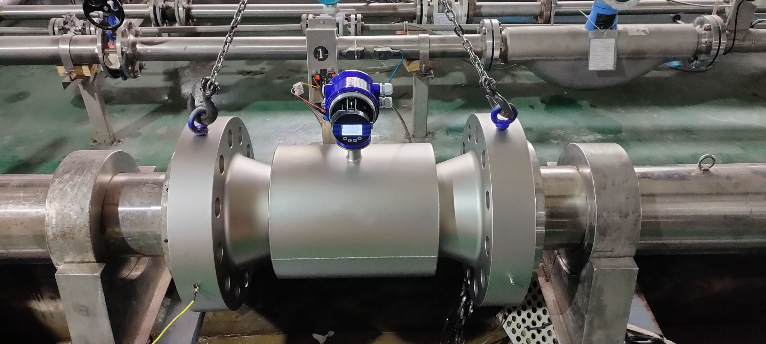
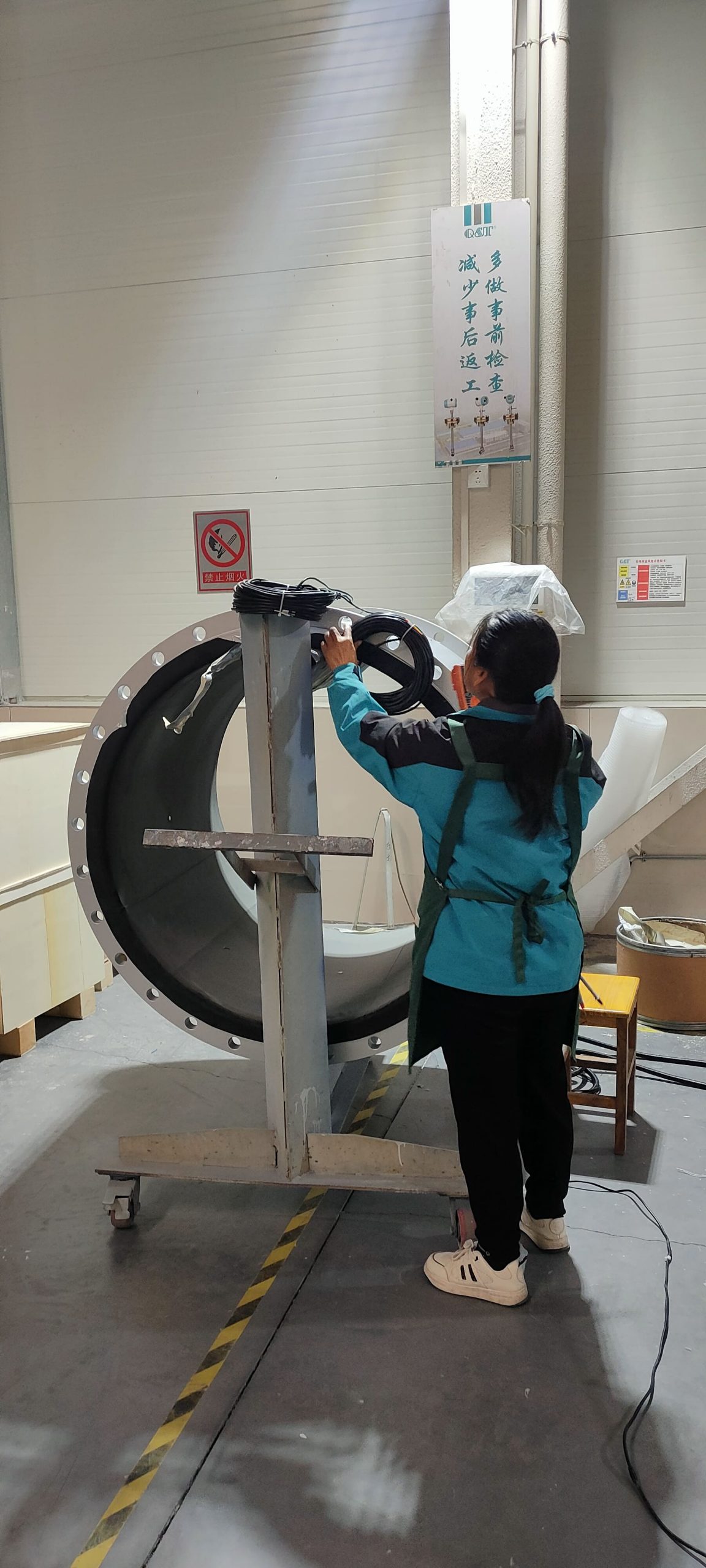
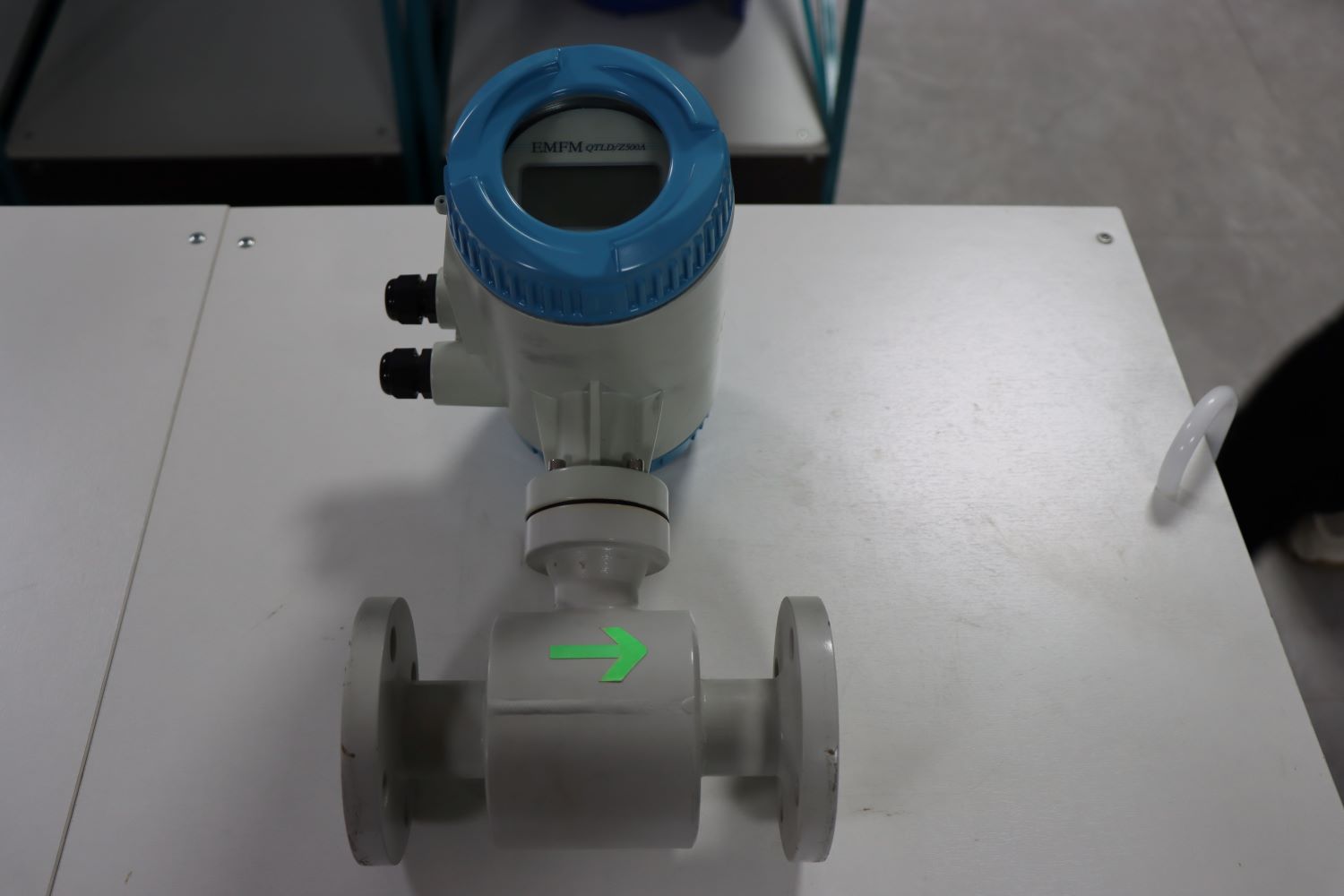
5. Install and use the ball valve onto the installation and usage base. Make sure the long cavity of the ball valve is facing upwards and check that the ball valve operates normally. Install the compression thread seat kit onto the ball valve, loosen the positioning screw and the compression nut, and insert the sensor insertion rod into the measured pipeline through the ball valve. The insertion depth of the sensor should extend 3mm beyond the base. After meeting the requirements, tighten the positioning screw and the compression nut. At the same time, pay attention to ensuring that the sensor direction mark is consistent with the fluid flow direction.
6. The opening on the pipe under test is larger than that on the base pipe, and the depth at which the base pipe is inserted into the opening of the pipe under test is such that the welds on both sides are level.
7. The insertable electromagnetic flowmeter is welded flat with stainless steel electrodes. After welding, ensure that the flange surface is parallel to the pipe axis.
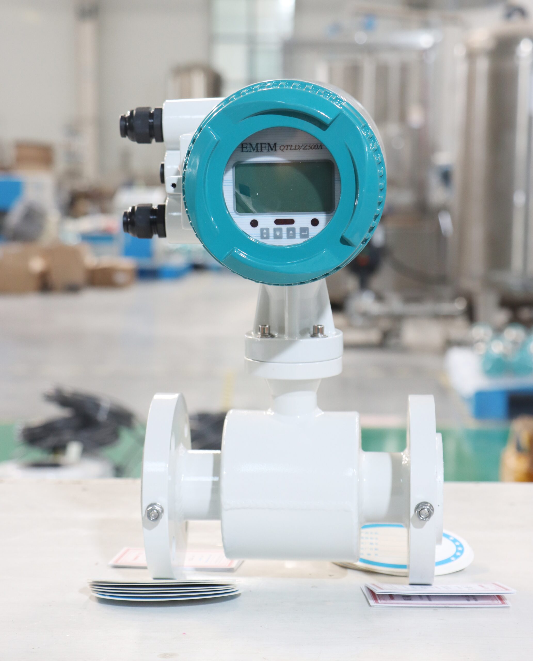
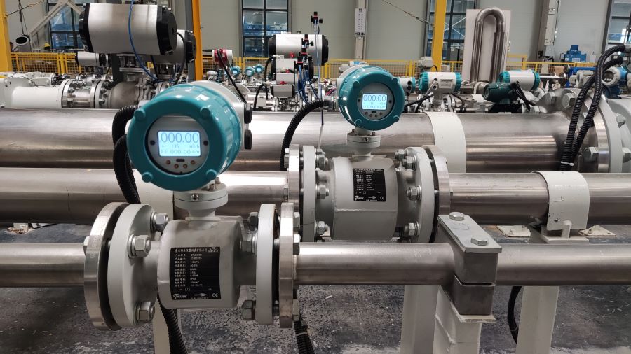
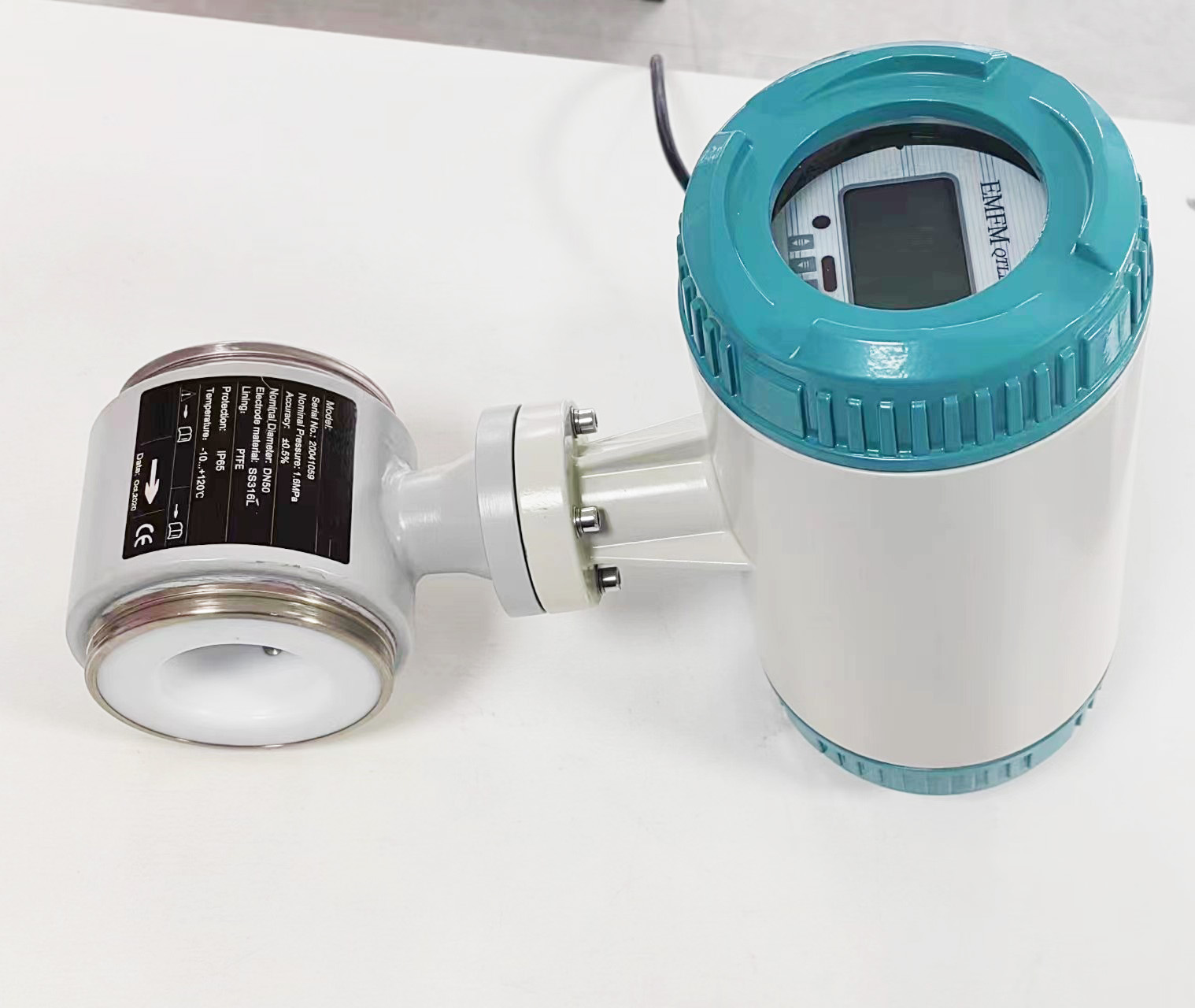
8. Connect the power supply and other wires to the converter gauge as per the standard in the manual of the insertable electromagnetic flowmeter. After powering on, check the instrument display. When it is confirmed that the measured pipe is filled with fluid and the flow rate is zero, check that the instrument display should be zero.
9. After the fluid in the tested pipe flows and stabilizes, check the instrument display. At this time, rotate the sensor direction to make the displayed value larger, and then lock the positioning screw and the compression nut.
10. For situations where the flow variation range is large and the fluid velocity is consistently lower than the standard low flow velocity of the flowmeter, it is advisable to consider reducing the process pipeline or using two flowmeters, one large and one small, installed in parallel for use.
11. Insertable electromagnetic flowmeters, like ordinary electromagnetic flowmeters, are suitable for installation and use on vertical process pipelines. This can prevent suspended solids from settling on the electrodes and at the same time cause the oil in the fluid to rise beyond the measurement range of the electrodes. If the flowmeter is installed and used on a horizontal process pipeline, the electrodes of the sensor should be on the horizontal axis Avoid the interference caused by bubbles on the electrode, which may lead to measurement errors.
12. For vertical installation and use, when the sensor is inserted into the pipeline, the Angle with the vertical diameter of the pipeline cross-section should be less than 5°. It is suitable for detecting clean media with small pipeline vibration.
13. It is installed and used at an Angle, with the sensor’s axis forming a 45° Angle with the axis of the pipe being measured. This method is suitable for flow detection of liquids with large pipe diameters and containing other impurities. This installation and usage method has low water resistance and is not suitable for entanglement.