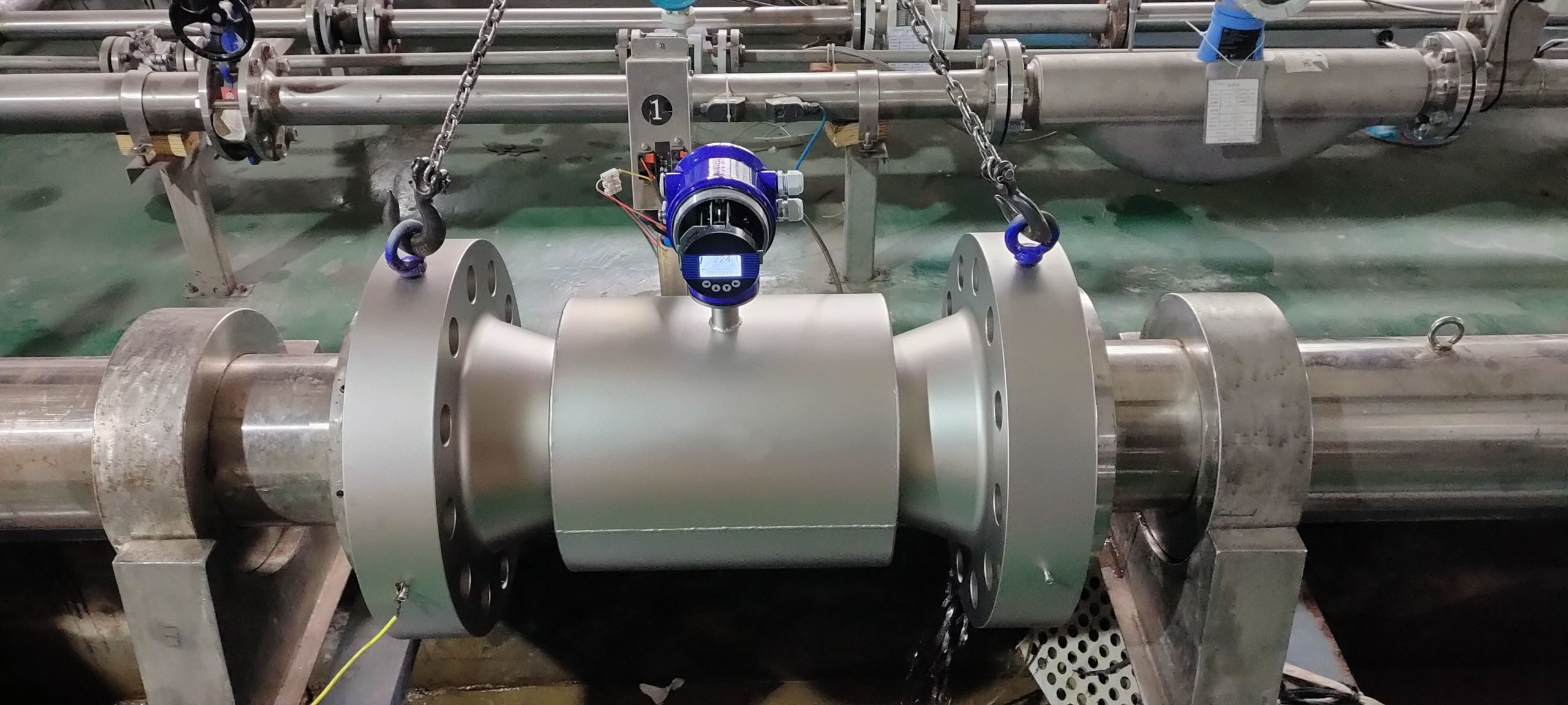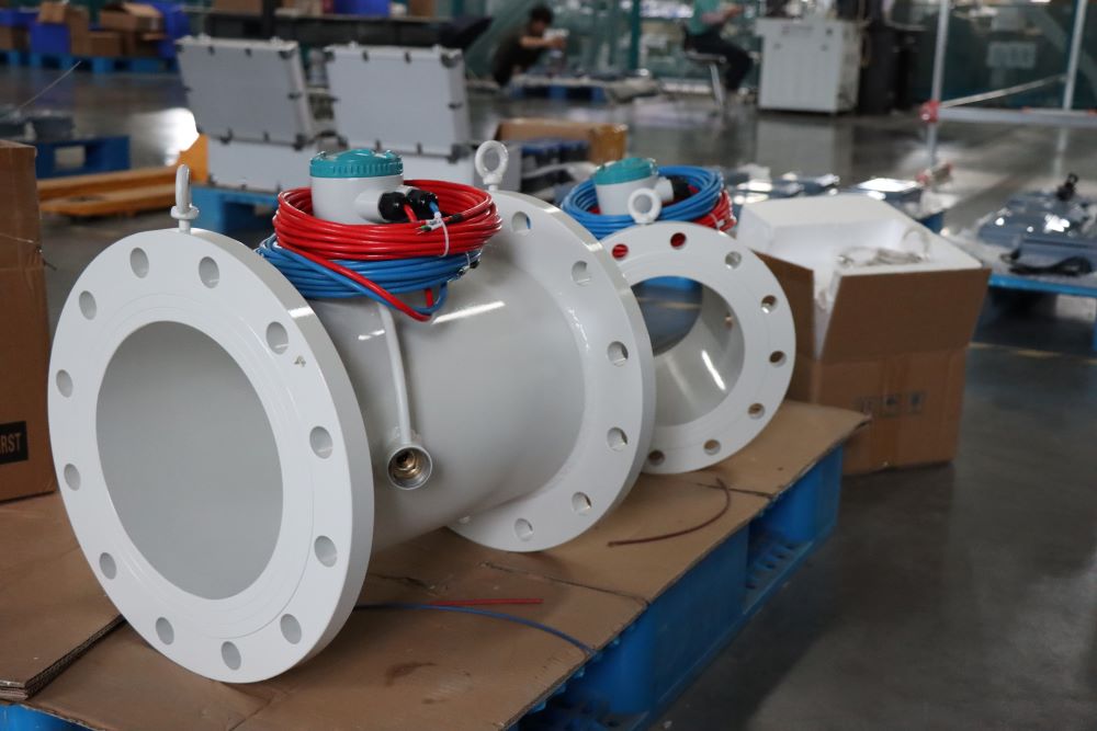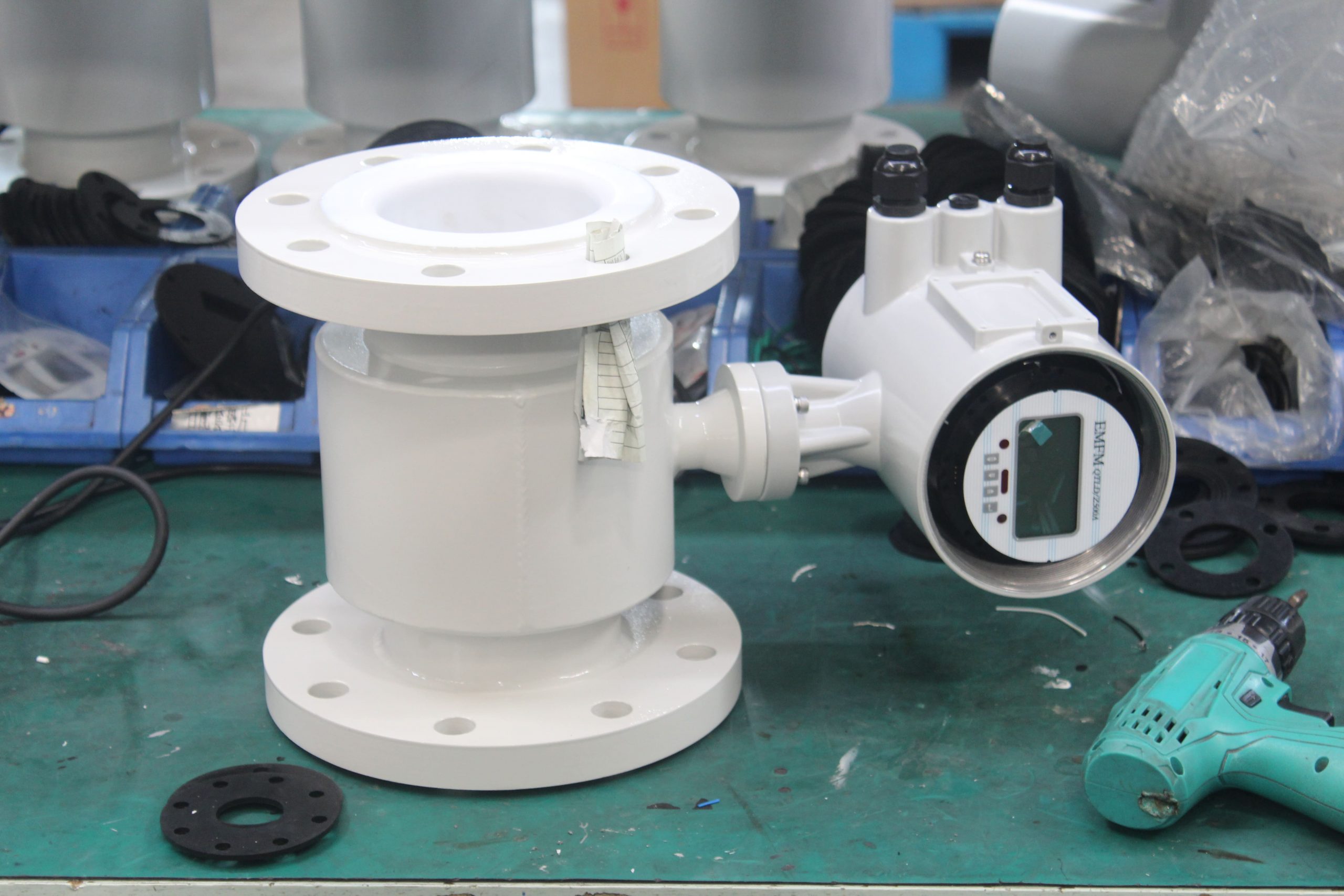
Installation requirements for electromagnetic flow meters
The installation direction of the electromagnetic flowmeter is not particularly strict requirements, generally horizontal, vertical or inclined can be unlimited. However, it must be reminded that in order to ensure that the pipeline is full of the measured medium, that is, the “full tube” state, it is recommended to install vertically, flow from bottom to bottom, especially for liquid-solid two-phase fluids, it must be installed vertically.
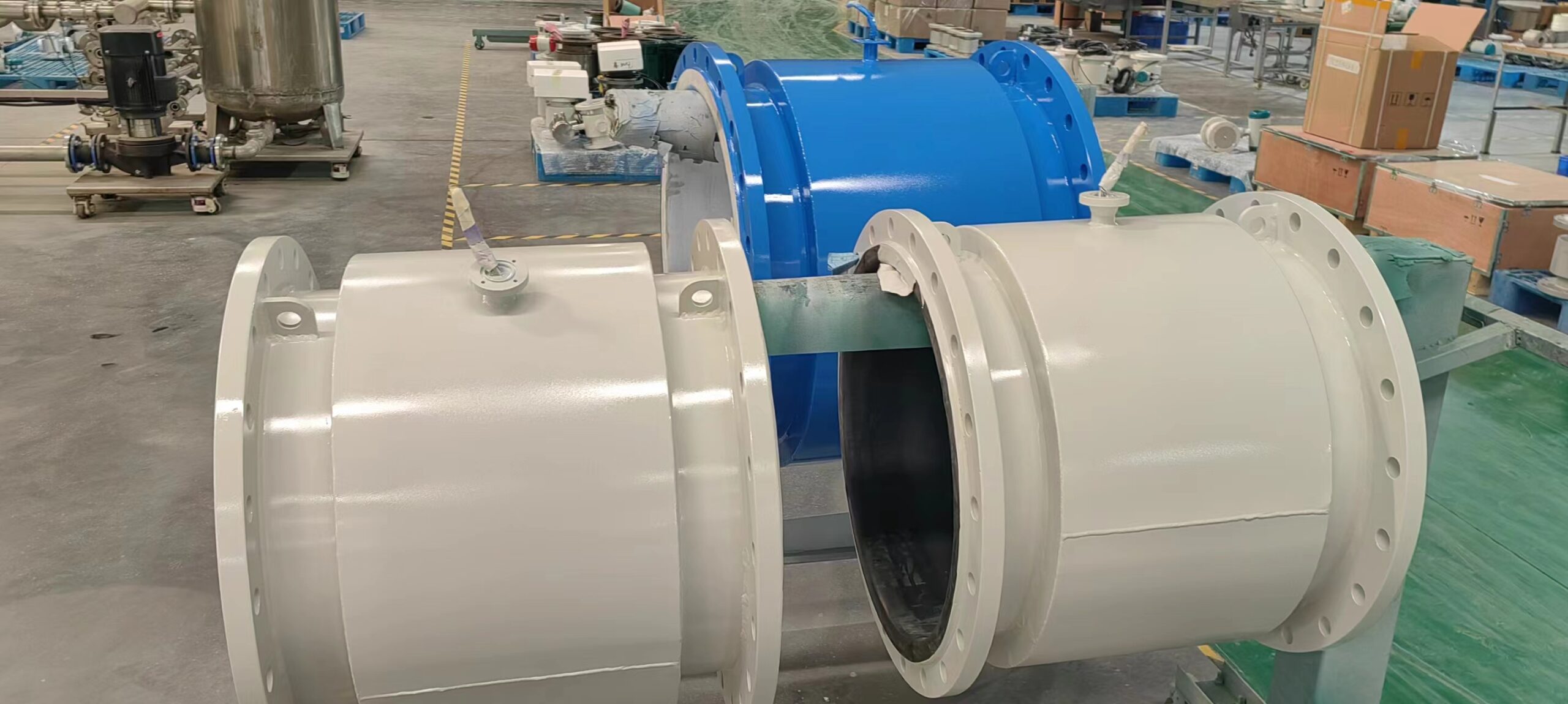
The installation direction of the electromagnetic flowmeter is not particularly strict requirements, generally horizontal, vertical or inclined can be unlimited. However, it must be reminded that in order to ensure that the pipeline is full of the measured medium, that is, the “full tube” state, it is recommended to install vertically, flow from bottom to bottom, especially for liquid-solid two-phase fluids, it must be installed vertically. If the site only allows horizontal installation, it must be ensured that the two electrodes are in the same horizontal plane, and the axis of the electrode must be approximately horizontal, because the electrode at the bottom is easily covered by sediment, and the top electricity is easily wiped by the occasional bubble in the liquid, covering the electrode surface and making the output signal fluctuate. The following lists the matters that need attention in the installation of electromagnetic flowmeters:
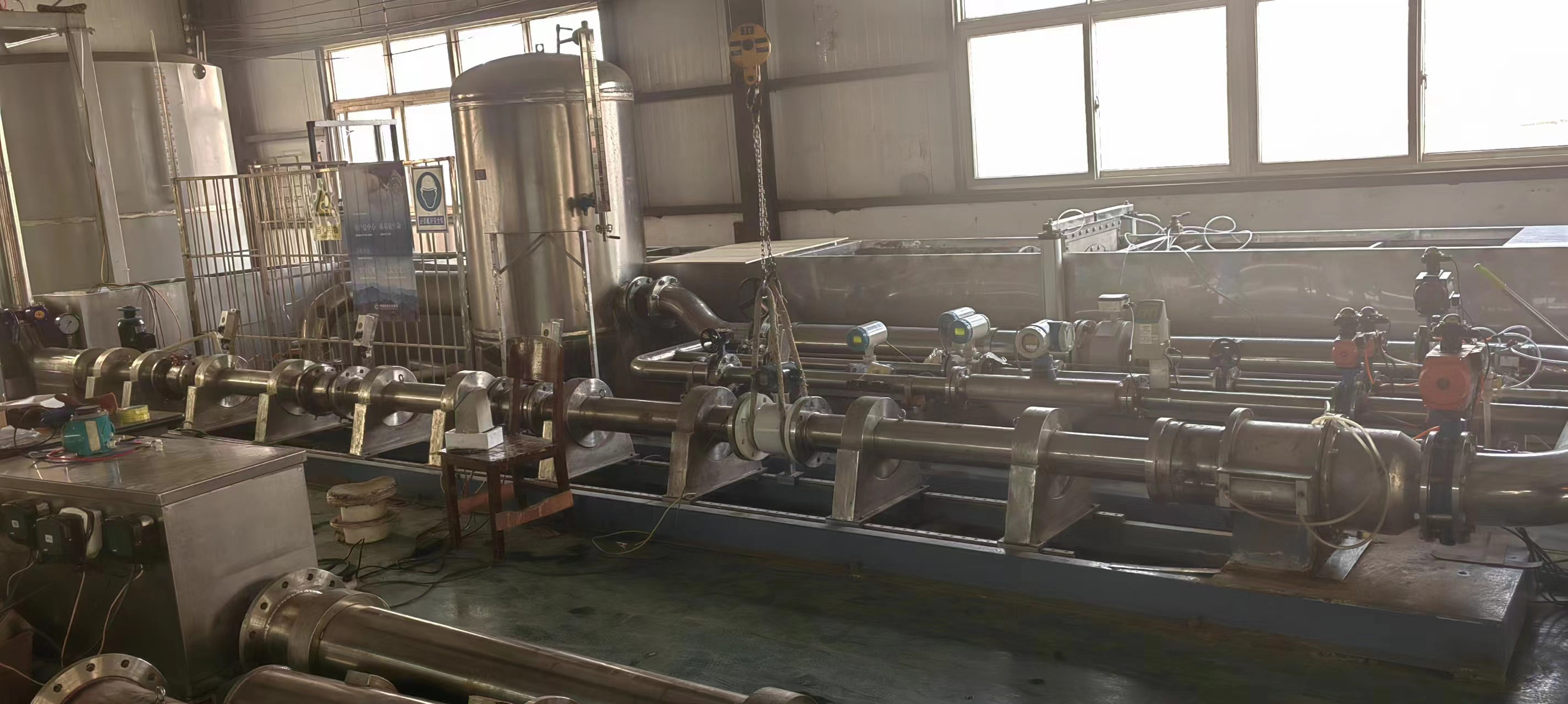
1, the upstream of the electromagnetic flowmeter is generally 10DN straight pipe section, the downstream has 5DN straight pipe section, at least 5DN straight pipe section, the downstream must have at least 3DN straight pipe section, in order to facilitate installation and disassembly, can be installed pipe expansion joint;
2. The flow direction of the fluid is consistent with the direction marked by the arrow on the flowmeter housing;
3, the flow meter should be as far away from the pump, valve and other equipment as possible to avoid its interference with the measurement;
4, the flow meter should be as far away from radio frequency, strong magnetic field, strong vibration and other interference sources as possible;
5, if the measuring pipe has vibration, there should be fixed supports on both sides of the flow meter;
6, in order to facilitate the cleaning and maintenance of the flow meter in the future, bypass pipes should be installed and the straight pipe section of the flow meter before 5DN and after 3DN should be ensured;
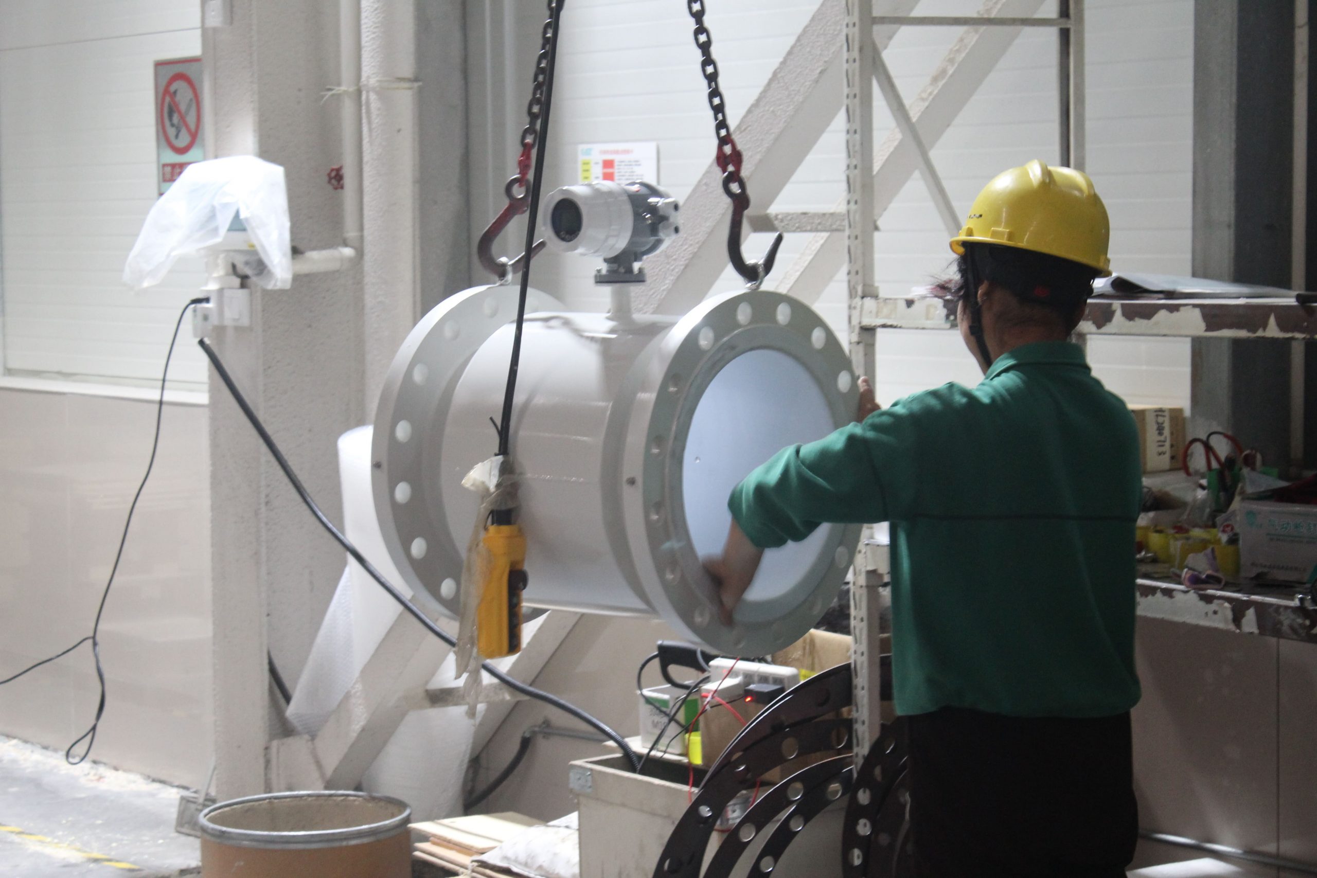
7, installation of electromagnetic flow timing, should pay attention to evenly tighten the two flanges, otherwise it is easy to crush the lining material;
8, the sensor must be individually grounded, under normal circumstances, the grounding resistance should be less than 100 euros, for explosion-proof products and lightning protection requirements of the installation, the grounding resistance should be less than 10 euros. In principle, the ground of the split flow meter should be on the sensor side, and the converter ground should be at the same ground point;
9, split electromagnetic flow meter converter is generally installed near the sensor or the distribution room, it should be noted that the sensor and the converter connection is, in order to avoid interfering with the signal, the signal cable must be worn separately in the grounding protection metal tube, can not be the signal and power cable mixed through the same metal tube.
-.jpg)

-.jpg)